


364985-XIM-B-0508
Johnson Controls Unitary Products 31
under field conditions would be inaccurate. To
assure a dry coil, the compressors should be deac-
tivated while the test is being run.
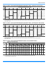
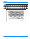
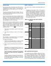
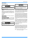
4. Knowing the pressure drop across a dry coil, the
actual CFM through the unit can be determined
from the curve in Pressure Drop vs. Supply Air
CFM (Figure 13).
After readings have been obtained, remove the tubes
and reinstall the two 5/16” dot plugs that were removed
in Step 1.
NOTE: De-energize the compressors before taking
any test measurements to assure a dry indoor
coil.
OPERATION
SEQUENCE OF OPERATIONS OVERVIEW
For these units, the thermostat makes a circuit
between “R” and “Y1” for the cooling cycle.
The call is passed to the unit control board (UCB),
which then determines whether the requested opera-
tion is available and, if so, which components to ener-
gize.
For heating, the thermostat makes a circuit between
“R” and “W1”. The UCB energizes the compressor and
condenser fan allowing the unit to run in heating mode.
A time / temperature control operates the defrost cycle.
If at any time a call for both heating and cooling are
present, the heating operation will be performed. If
operating, the cooling system is halted as with a com-
pletion of a call for cooling. Heating always takes prior-
ity.
COOLING SEQUENCE OF OPERATION
CONTINUOUS BLOWER
By setting the room thermostat fan switch to “ON,” the
supply air blower will operate continuously.
INTERMITTENT BLOWER
With the room thermostat fan switch set to “AUTO” and
the system switch set to either the “AUTO” or “HEAT”
settings, the blower is energized whenever a cooling or
heating operation is requested. The blower is ener-
gized after any specified delay associated with the
operation.
When energized, the indoor blower has a minimum run
time of 30 seconds. Additionally, the indoor blower has
a delay of 10 seconds between operations.
NO OUTDOOR AIR OPTIONS
When the thermostat calls for cooling, the low-voltage
control circuit from “R” to “Y1” and “G” is completed.
The compressor and condenser fan motor are ener-
gized. After completing the specified fan on delay for
cooling, the UCB will energize the blower motor.
Once the thermostat has been satisfied, it will de-ener-
gize Y1. If the compressor has satisfied its minimum
run time, the compressor and condenser fan de-ener-
gize. Otherwise, the unit operates the cooling system
until the minimum run time for the compressor has
been completed. After the compressor de-energizes,
the blower is stopped following the elapse of the fan off
delay for cooling.
To be available, a compressor must not be locked-out
due to a high or low-pressure switch or freezestat trip
and the anti-short cycle delay (ASCD) must have
elapsed.
Failure to properly adjust the total system air
quantity and static pressure can result in
extensive system damage.
FIGURE 13 - PRESSURE DROP ACROSS COIL
0
0.1
0.2
0.3
0.4
0.5
1000 1500 2000 2500 3000
036
048
060
PRESSURE DROP (IWG)