


364985-XIM-B-0508
24 Johnson Controls Unitary Products
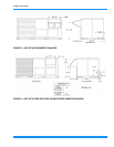
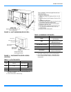
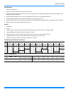
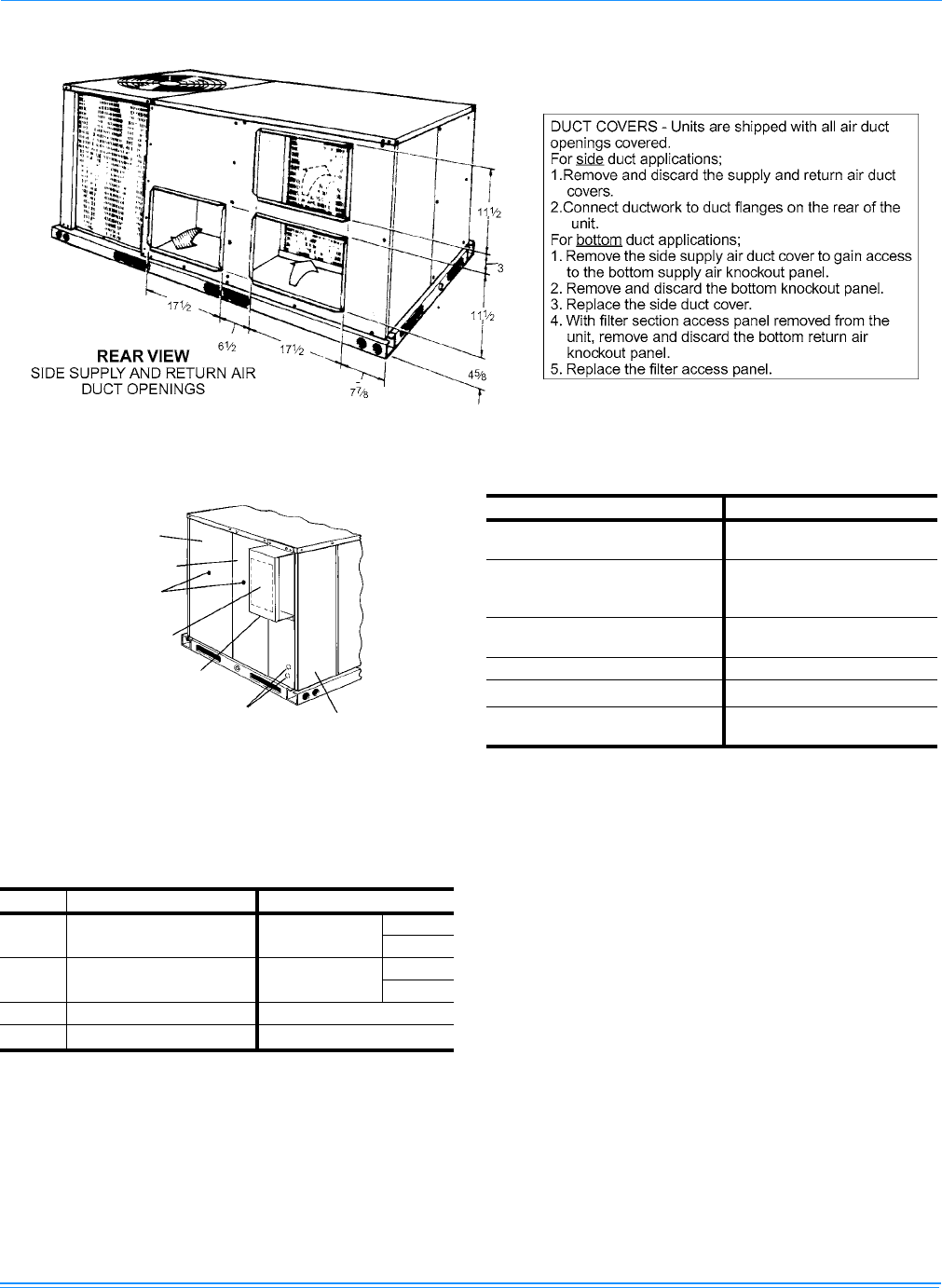
FIGURE 10 - UNIT DIMENSIONS (REAR VIEW)
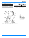
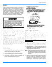
FIGURE 11 - DISCONNECT/BLOWER ACCESS
LOCATION
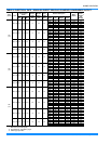
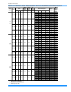
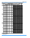
TABLE 17: UTILITIES ENTRY
HOLE OPENING SIZE (DIA.) USED FOR
A
7/8” KO
1
Control Wiring
2
Side
Bottom
B
2” KO
1
Power Wiring
Side
Bottom
C
1-5/8” KO Gas Piping (Front)
D
1-1/2” KO
Gas Piping (Bottom)
1. Opening in the bottom to the unit can be located by the
side in the insulation.
2. Do not remove the 2” knockout ring.
Disconnect Switch Location
and Motor Access Panel for
Unit with “Belt-Drive” Option
Control Box Access
A,B
Wiring Entry
(See Detail “B”)
Mounting Bracket for
Disconnect Switch
(Field Supplied)
Field-Supplied Disconnect
Switch Location
Blower Motor Access
Filter Access
Dot Plugs
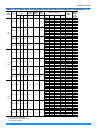
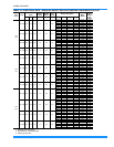
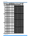
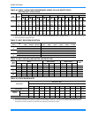
TABLE 18: MINIMUM CLEARANCES
LOCATION
CLEARANCE
Front
24” (Cooling/Electric Heat)
32” (Gas Heat)
Rear
12” (Less Economizer)
36” (With Economizer or Fixed
Air/Motorized Damper)
Left Side (Filter Access)
24” (Less Economizer)
36” (With Economizer)
Right Side (Cond. Coil)
24”
Below Unit
1
0”
Above Unit
2
72” (For
Condenser Air Discharge)
1. Units may be installed on combustible floors made
from wood or class A, B, or C roof covering material.
2. Units must be installed outdoors. Overhanging struc-
tures or shrubs should not obstruct condenser air dis-
charge outlet.