5
8. Maintenance
FAILURE TO DISCONNECT AND
LOCKOUT ELECTRICAL POWER
BEFORE ATTEMPTING ANY
MAINTENANCE CAN CAUSE
SHOCK, BURNS OR DEATH.
1. Bearings are located in and are part of the motor. For
lubrication procedure, refer to manufacturer’s instruc-
tions.
2. On frame-mounted units, regrease at 2,000 hours use
or after 3 months. Use #2 Sodium or Lithium grease
and fill until grease comes out of the relief fitting.
9. Disassembly
1. Always turn power off.
2. Drain system. Flush if necessary.
3. Remove motor hold-down bolts on close-coupled or
disconnect coupling and remove spacer.
4. Remove casing bolts and pump hold-down bolts.
5. Remove motor and rotating element from casing.
6. Unscrew impeller bolt with a socket wrench. Do not
insert screwdriver between impeller vanes to prevent
rotation. It may be necessary to use a strap wrench
around the impeller if impacting the socket wrench
will not loosen the impeller bolt.
7. Remove impeller o-ring.
8. Insert two pry bars (180º apart) between impeller and
seal housing. Pry off impeller.
9. Remove shaft sleeve, seal spring, cupwasher, seal
rotary and impeller key.
10. Remove seal housing.
11. Place seal housing on flat surface. Press out stationary
seal parts.
12. Remove deflector from shaft on frame-mounted
units.
13. Remove bolts holding bearing cover to frame and
remove bearing cover (frame-mount).
14. Remove lip seals from bearing frame and bearing
cover (frame-mount).
15. Remove shaft and bearings from frame (frame-
mount).
16. Remove bearing retaining ring (frame-mount).
17. Use bearing puller or arbor press to remove ball
bearings (frame-mount).
18. Remove wear ring if excessively worn. Use pry bar
and/or vicegrips.
10. Reassembly
1. All parts should be cleaned before assembly.
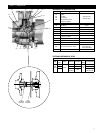
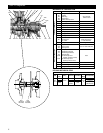
2. Refer to parts list to identify required replacement
items.
3. Reassembly is the reverse of the disassembly proce-
dure.
4. Replace lip seals if worn or damaged (frame-mount
only).
5. Replace ball bearings if loose, rough or noisy when
rotated (frame-mount only).
6. Check shaft for maximum runout of .005" TIR. Bear-
ing seats and lip seal areas must be smooth and free of
scratches or grooves. Replace if necessary (frame-
mount only).
7. All mechanical seal components must be in good
condition or leakage may result. Replacement of
complete seal assembly, whenever seal has been
removed, is good standard practice.
8. If wear ring is being replaced, do not use lubricants on
the metal-to-metal fit when pressing in the replace-
ment.
9. If the impeller is removed, as for example to effect a
mechanical seal change, this procedure must be
followed: Old impeller bolt and impeller o-ring cannot
be reused.
10. Install the mechanical seal stationary seat in the seal
housing, using soapy water as a lubricant to ease
insertion.
11. S-Group – Install the mechanical seal spring retainer,
spring and rotary assembly on the shaft sleeve using
soapy water to lubricate. Slide the shaft sleeve over
the pump shaft, be sure that a new shaft sleeve o-ring
is used.
NOTE: THE SHAFT SLEEVE O-RING AND IMPEL-
LER WASHER O-RING ARE ALMOST
IDENTICAL IN DIAMETER. BE SURE TO
USE THE SQUARE CROSS-SECTION
O-RING IN THE IMPELLER WASHER. THE
ROUND CROSS-SECTION O-RING IS USED
IN THE SHAFT SLEEVE.
11. M-Group – Install the mechanical seal spring and
rotary on the shaft sleeve using soapy water to lubri-
cate. Slide the shaft sleeve over the pump shaft. Be
sure that a new shaft sleeve o-ring is used. Place the
mechanical seal spring retainer over the impeller hub.
12. Place the impeller key into the shaft keyway and slide
the impeller in place. Install the impeller stud and
impeller washer. Be sure that a new impeller o-ring is
used. Tighten S-Group (
3
⁄
8
" thread) to 17 lb.ft. and
M-Group (½" thread) to 38 lb.ft.
13. Replace casing bolts and tighten in a crossing se-
quence to the torque values indicated below.
S-Group – 25 lb.-ft. (35 N-m)
M-Group – 37 lb.-ft. (50 N-m)
14. Check reassembled unit for binding by rotating shaft
with appropriate tool from motor end.
15. If rubbing exists, loosen casing bolts and proceed
with tightening sequence again.
WARNING
Hazardous
voltage


