


6
Section 3 (continued)
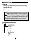
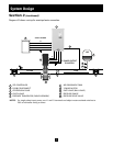
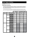
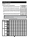
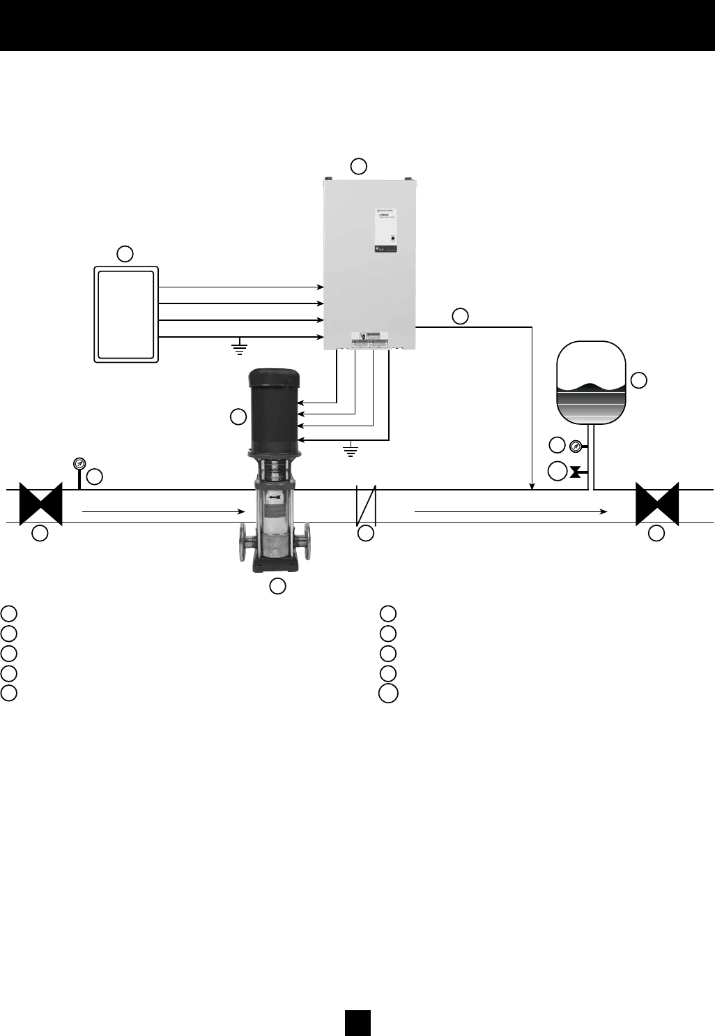
Diagram#2showsaset-upformunicipalwaterconnection.
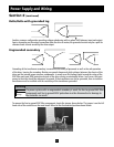
System Design
FLOW
AIR
4
8
6
3 PHASE OUTPUT
TO MOTOR
5
1
2
SUCTION
3
8
9
7
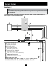
1 SPD CONTROLLER 6 AIR DIAPHRAGM TANK
2 FUSIBLE DISCONNECT 7 3 PHASE MOTOR
3 CENTRIFUGAL PUMP 8 GATE VALVE (BALL VALVE)
4 CHECK VALVE 9 PRESSURE GAUGE
5 PRESSURE TRANSDUCER (CABLE ASSEMBLY) 10 PRESSURE RELIEF VALVE
NOTES: For single phase input power, use L1 and L3 terminals and adjust motor overload switches to
50% of controller rating or lower.
9
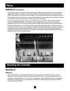
T1
T2
T3
L1
L2
L3
SUPPLY POWER
GND
GND
10