


22
Troubleshooting
Red Light Codes (continued)
Flashes Controller Status Description
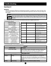
3Blinks(contd.) -DisconnecttheWhitewireinthesensorcablefromterminal6.
-SetthemetertoreadDCcurrent(mA)
-Connecttheblackleadfromthemetertoterminal6
(TRANSDUCERINPUT)
-ConnecttheredleadfromthemetertotheWhitewireinthe
sensorcable.
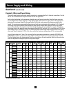
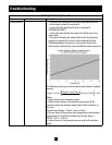
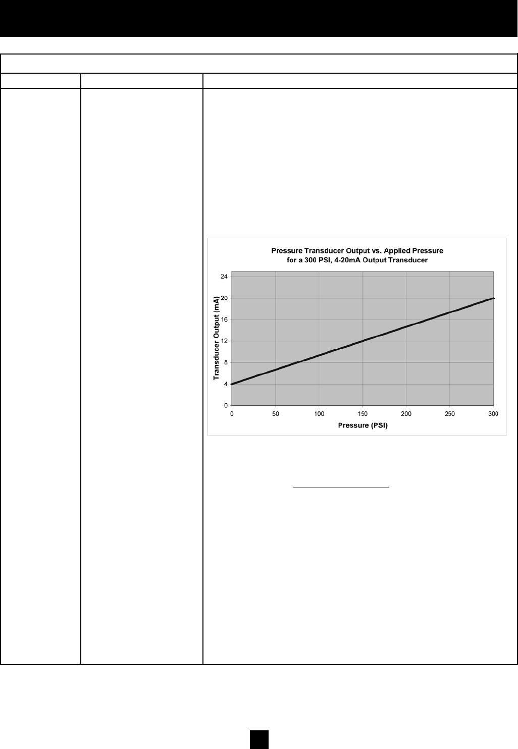
-Themeterwilldisplaytheoutputofthesensor.Iffunctioning
properly,theoutputofthesensorwillbebetween4mAand
20mAdependingonthepressureinthesystem.Refertothe
chartbelowtodeterminethesensorfeedbackatvariouspressures.
Thefollowingformulagivesthetransduceroutputbasedonapplied
pressure:
Output Current =
Output Current Range
x System Pressure + 4mA
Pressure Range
Where:
•OutputCurrentisthetransduceroutput
•OutputCurrentRangeisthemaximumoutputsignalofthe
transducerminustheminimumoutputsignalofthetransducer.In
thiscase:
OutputCurrentRange=20mA–4mA,or16mA
•PressureRangeisthepressurethatcorrespondstothemaximum
outputsignal.Fora300PSItransducerthePressureRange=
300PSI–0PSI=300PSI
•SystemPressureisthesystempressureasreadonthepressure
gauge.
[ ] ( )