


21
Troubleshooting
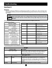
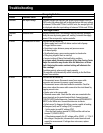
Orange Light Codes
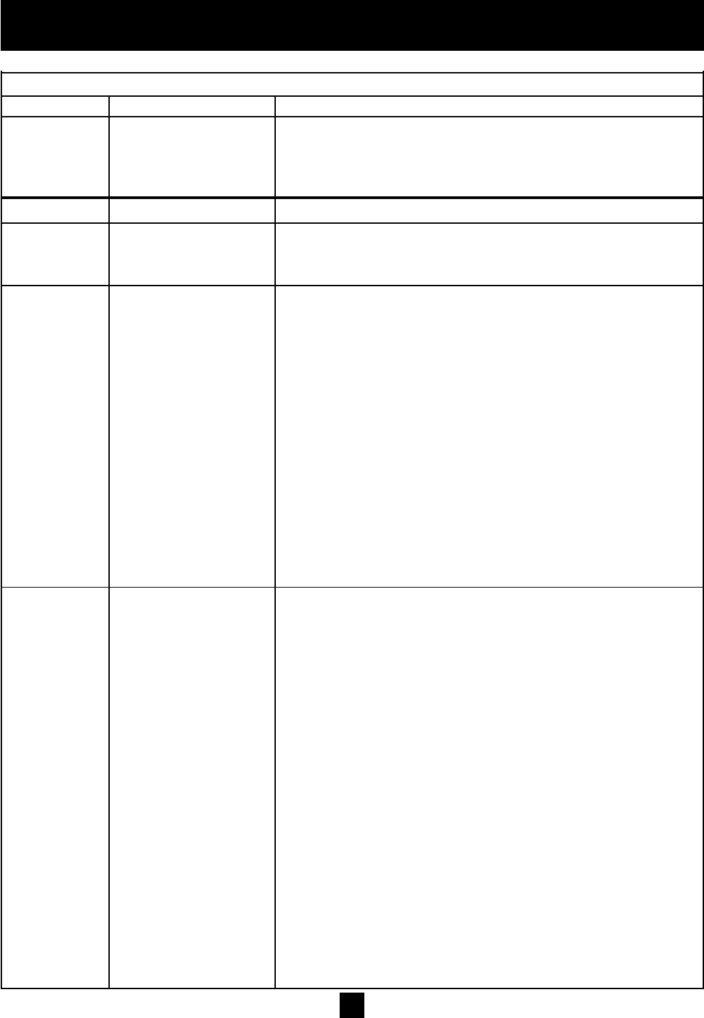
Flashes Controller Status Description
Constant LowInputVoltage Constantorangelightindicatesthesysteminputvoltageislow.For
230Vunits,theorangelightwillbeindicatedwhentheinputvoltage
isbetween140Vacand170Vac.For460Vunits,theorangelightwill
bedisplayedwhentheinputvoltageisbetween140Vacand310Vac.
Red Light Codes
Constant ControllerError Internalcontrollerfault.Thecontrollermaybeinternallydamaged.
Red Verifytheerrorbyturningpoweroff,waiting5minutesthenapply
power.Iftheerrorpersists,replacecontroller.
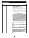
2Blinks NoWater/LossOfPrime Thisfaultcanbecausedby:
•Watersupplylevelinwellfallsbelowsuctioninletofpump.
•Pluggedsuctionscreen.
•Restrictioninpipebetweenpumpandpressuresensor.
•Airboundpump.
•Deadheadedpump,pumprunningagainstaclosedvalve.
•Fillinglongirrigationlinesonstart-up
•IncorrectsettingofMotorOverloadSettingswitches.
In systems where the motor operates at less than Service Factor
Amps the controller may show a false No Water/Loss of Prime
fault. Reducing the motor overload setting will eliminate the
false readings.
Ifproblempersists,pleaseverifysupplycapacity.
ThecontrollerwillautomaticallyrestartaccordingtotheNoWater
RestartTimeswitches.
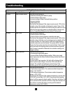
3Blinks SensorFault Thisfaultcanbecausedby:
•Disconnectedsensor.Disconnectsensorfromsensorcable
connectorandreconnecttoensureagoodconnection.
•Disconnectedsensorcableleadinsidethecontroller.Checkfor
loosewireswherethesensorcableconnectstothecircuitboardby
tuggingoneachwire.
•Brokenwireinthesensorcable.
•Miswiredsensorcable.Checkthatthewiresareconnectedtothe
correctterminalsonthecontrolterminalblock.Connectterminal
7(24VDCSUPPLY)totheBrownwire.Connectterminal6(TRANSDUCER
INPUT)totheWhitewire.Connectthedrainwiretochassis.
•Failedsensor.Todiagnosethisfailureametercapableofreading
milliamperes(mA)andDCvoltage(VDC)isrequired.
-SetthemetertoreadDCvoltage(VDC)
-Placetheblackleadonterminal5(COM)andtheredleadon
terminal7(24VDCSUPPLY)
-Iffunctioningproperly,theDCvoltagewillbe24VDC+/-15%.If
thisvoltageisnotpresent,disconnectallcontrolterminalsand
repeatthemeasurement.Ifvoltagedoesnotrecover,replace
controller.