


Page 7 of 8PH10A-XXX-XXX (en)
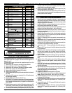
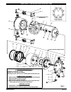
PARTS LIST / PH10A-XXX-XXX AIR MOTOR SECTION
Figure 3
127
201
l 126
109
j
111
102 jm
103
118
137
j
136
109
121
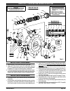
MAJOR VALVE
See cross section detail figure 4.
PILOT
VALVE
MAJOR VALVE
CROSS SECTION DETAIL
110 j
104123 k
j
110
112
j
114
j
113
115 116
112
j 113
j 114
115
116
j 111
j 137
Figure 4
102 jm
136
LUBRICATION / SEALANTS
j Apply Key-Lube grease (93706-1)
to all “O” rings, “U” Cups & mat-
ing parts.
k Apply Loctite 271 to threads.
l Apply Loctite 572 to threads.
m Refertosteps1and2of“Pilot
Valve Reassembly”.
101
104
123 k
174 j
173 j
118
169
j
121
173 j
174 j
126 l
167
j 168
170
j 172
j 171
IMPORTANT
BE CERTAIN TO ORIENT (115) SPACER LEGS
AWAY FROM BLOCKING INTERNAL PORTS
WHEN REASSEMBLING AIR SECTION.
MAJOR VALVE DISASSEMBLY
1. Remove the two (124) tie rods blocking the (136) plugs.
2. Using a 3/8” Allen wrench, remove both (136) plugs. Check the
(137) “O” rings and make certain they are intact and undamaged.
Fragments of “O” rings can cause the pump to malfunction.
3. From the airinletside (use a largedoweland soft mallet) tap moder-
ately on the (109) piston and thenpush the entire valvestackout the
opposite side. Clean and inspect all parts for damage and wear.
MAJOR VALVE REASSEMBLY
S
Lubricate allsoft parts,spool, andbores with Key-Lubegrease upon
reassembly.
1. For best results, rebuild the Major Valve stack one piece at a time.
Start with the (112) washer and install it in the side opposite the air
inlet. Place the washer into the bore with the raised edge facing out-
ward, follow it with the larger (114) “O” ring.
2. Place (113) “O” ring on the (115) spacer, insert the spacer with the
legs facing outward, be sure not to block the internal ports with
the
spacer legs
. Repeatthisprocess threetimes and makecertaineach
set is pressed in well.
3. Install the last (112) washer and a (114) “O”ring, place the last (113)
“O” ring on the (116) spacer and install. Install the last (114) “O” ring.
4. Lubricate the (111) spool and install (this is the side opposite of the
air inlet). Note: The end with the hole in it faces outward.
5. Install a new (137) “O” ring on the (136) plug and thread it into the
(101 motor center body.
S Note: Align plug carefully and take care not to damage “O” rings.
6. Assemble the (110) “U” cup to the (109) piston and install it into the
air inlet side with the lips facing outward.
7. Install new (137) “O” ring on the (136) plug and install into the (101)
motor center body.
8. Assemble (124)tie rods,securing with(29) nuts. NOTE:Torque(29)
nuts to 280 - 300 in. lbs (31.6 - 33.9 Nm).