


PH10A-XXX-XXX (en)Page 4 of 8
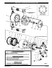
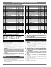
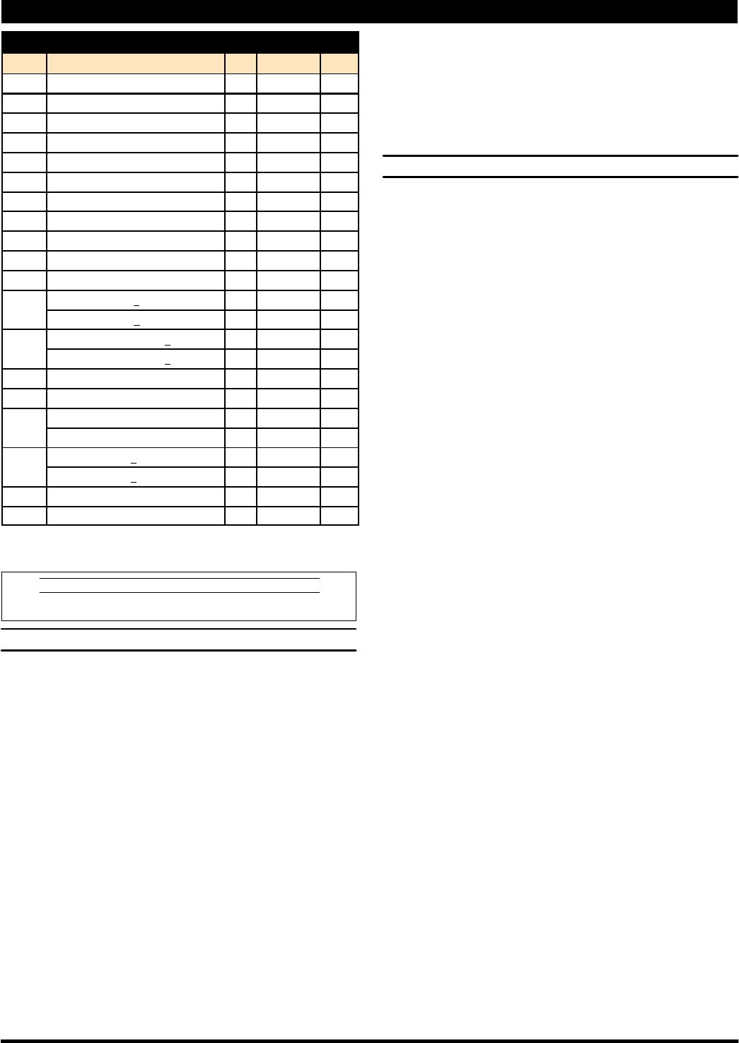
PARTS LIST / PH10A-XXX-XXX FLUID SECTION
FLUID SECTION PARTS
Item Description (size) Qty Part No. [Mtl]
L Fluid Section Service Kit 637339-( )
V 1 Rod (1) 98724-1 [C]
n 2 “O” Ring (3/32” x 3/4” o.d.) (1) Y330-113 [B]
L 3 “O” Ring (3/32” x 11/16” o.d.) (4) Y328-112 [T]
V 5 Plate (2) 94074-1 [C]
V 6 Diaphragm Plate (2) 94055 [SS]
L 7 Diaphragm (2) 94800 [T]
9 Washer (1.375” o.d. x 0.505” i.d.) (2) 93189-1 [SS]
14 Bolt (1/2” - 20 x 1-1/2”) (2) Y5-87-T [SS]
15 Fluid Cap (2) 95191 [SS]
L 19 “O” Ring (3/32” x 1-9/16” o.d.) (4) Y328-126 [T]
L 21 Seat (PH10A-XSS-SXT) (4) 90428 [SS]
(PH10A-XSS-HXT) (4) 93367-1 [SH]
L 22 Ball (1” dia.) (PH10A-XSS-XST) (4) 90948 [SS]
(PH10A-XSS-XHT) (4) Y16-132 [SH]
26 Cap Screw (M8x1.25x25mm) (8) 95177 [SS]
29 Flange Nut (M8x1.25) (16) 95535 [C]
32 Bracket, Right Side (2) 94154-1 [C]
Bracket, Left Side (2) 94154-2 [C]
V 36 Manifold (PH10A-ASS-XXT - N.P.T.F.) (2) 94394 [SS]
(PH10A-BSS-XXT -BSP) (2) 94394-1 [SS]
43 Ground Lug (1) 93004 [Co]
67 Screw (1/4” - 20 x 5/8”) (1) 93860 [SS]
V “Smart Parts”, keep these items on hand in addition to the service kits for fast repair
and reduction of down time.
n Indicates parts included in 637338 air section service kit.
MATERIAL CODE
[B] = Nitrile [Co] = Copper [SS] =Stainless Steel
[C] = Carbon Steel [SH] = Hard Stainless Steel [T] = PTFE
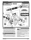
FLUID SECTION DISASSEMBLY
The followingprocedure is for the installationof Fluid SectionServiceKit
parts. Refer to the view on page 5. The items with three digits are on
pages 5, 6 and 7.
The steps shown below are for one side, repeat the steps 7 thru 12 to
service the other side.
1. Remove four (26) cap screws, releasing (36) top manifold.
2. Remove (22) balls, (19) “O” rings and (21) seats.
3. Remove four (26) cap screws, releasing (36) bottom manifold.
4. Remove (19) “O” rings, (21) seats and (22) balls.
5. Remove eight (29) nuts, releasing (32) brackets.
6. Remove one (15) fluid cap.
7. Using a plastic mallet, tapthe (124) tie rods back flush into theauxil-
iary body.
8. Remove two(158) capscrews,releasing (154or 155) auxiliarybody
and diaphragm assembly.
9. Remove (159) “O” ring and one (153) “O” ring.
S SERVICENOTE: Thenextfewsteps relateonlytodiaphragmdisas-
sembly. Further disassembly wouldnotnormally be required unless
there is damage /wear found onthe (148) pistonor onthe face ofthe
(152) cylinder.
10. Using a spanner wrench to hold the (149) adapter piston and a 3/4”
socket on the (14) bolt, remove the (14) bolt, releasing ( 9) washer, (3)
“O” ring, (6) diaphragmplate, (7) diaphragm, (5) plate and(3) “O” ring.
11. Remove the piston assembly andinspect the (151) nut, (148) piston
assembly, (150) “O” ring and (149) adapter piston. Do not disas-
semble further unless damage is evident.
12. Using an “O” ring pick, remove the (165) quad ring and two (164)
back-up rings from the (163) bushing.
S SERVICE NOTE: Removal of the (163) bushing should not be nec-
essary, howeverit must bechecked forsharpedges andremoved to
prevent possible further damage.
FLUID SECTION REASSEMBLY
S
Clean all parts upon reassembly. Lubricate all replacement parts
and metallic moving parts with Key-Lube grease upon reassembly.
S SERVICE NOTE: PTFE “O” rings are not resilient and they should
always be replaced with new ones.
1. Install the (164) back-up ring by pulling it apart, twist or walk it down
into the cavity bottom inside the (163) bushing.
2. Install the (165) quad ring on top of the spiral ring by folding it in half
allowing it to get past the bushing i.d. and into the cavity.
3. Install the second (164) back-up ring as in step 1. Locate it on top of
the quad ring. Lubricate and smooth out the set with your finger to
assure good alignment.
4. Place the (9) washer onto the (14) bolt, with thechamfer against the
bolt head, place the (3) “O” ring onto the (14) bolt and insert these
three parts thru the (6) plate.
5. Place the (7) diaphragm onto this assembly, (see assembly note,
page 5).
6. Assemble the (150) “O” ring and (148) piston assembly to the (149)
adapter piston, securing with the (151) nut.
7. Lubricate the (152) cylinder wall and insert the piston assembly into
the cylinder and through the bushing / quad seal.
8. Apply LoctiteR #271t to theinner threads ofthe(149) adapterpis-
ton.
9. Place the (3) “O”ringon theend ofthe(149) adapterpiston and slide
the (5) plate over it.
10. Thread the piston assembly and diaphragm assembly together.
Hold the piston assembly with a spanner wrench, align the dia-
phragm with the bolt holes and torque the (14) bolt to 49 - 52 ft lbs
(66.4 - 70.5 Nm).
11. Install the (159) “O” ring and the (153) large “O” ring. Assembly hint:
A liberal amount of Key-Lube grease will hold these in place tempo-
rarily.
12. Align the (154 or 155) auxiliary body with the (125) dowel pin and
(158) cap screws, and push together, securing with two (158) cap
screws.
S CAUTION: The tie rods can tear the diaphragm and ruin it. Hold the
diaphragm against the pump body with your fingers when pushing
each rod end through.
13. Align the diaphragm with the proper holes in the body and push the
rods throughfar enoughto allowinstallation ofthe(15) fluidcaps. Be
certain the flow direction is oriented correctly.
14. Assemble four (29) nuts.
15. Install two (32) brackets, securing with four (29) nuts.
S NOTE: Tighten the fluid cap nuts in a cross pattern alternately and
evenly. Torque (29) nuts to 280 - 300 in. lbs (31.6 - 33.9 Nm).
16. Assemble (22) balls, (21) seats and (19) “O” rings into the cavity i n
the bottom of (15) fluid caps.
17. Assemble (36) bottom manifold to fluid caps, securing with (26) cap
screws. NOTE: Torque (26) cap screws to 120 - 140 in. lbs (13.6 -
15.8 Nm).
18. Assemble (21) seats, (19) “O” rings and (22) balls into the cavity in
the top of (15) fluid caps.
19. Assemble (36) top manifold to fluid caps, securing with (26) cap
screws. NOTE: Torque (26) cap screws to 120 - 140 in. lbs (13.6 -
15.8 Nm).