


PH10A-XXX-XXX (en)Page 6 of 8
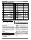
PARTS LIST / PH10A-XXX-XXX AIR MOTOR SECTION
n Indicates parts included in 637338 Air Section Repair Kit.
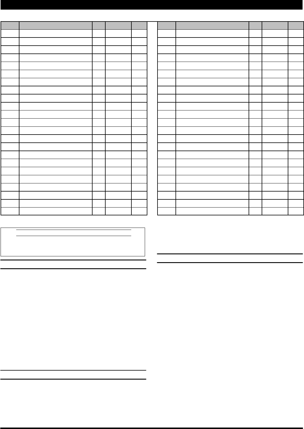
Item Description (size) Qty Part No. Mtl Item Description (size) Qty Part No. Mtl
101 Motor Center Body (1) 95122-1 [A]
n 102 “O” Ring (1/16” x 1” o.d.) (2) Y325-20 [B]
V 103 Sleeve (1) 94527 [D]
104 Plate (2) 95125 [SS]
109 Piston (1) 92011 [D]
n 110 “U” Cup (3/16” x 1-3/8” o.d.) (1) Y186-51 [B]
111 Spool (1) 92005 [A]
112 Washer (1.556” o.d.) (5) 92877 [Z]
n 113 “O” Ring (small) (1/8” x 1-1/4” o.d.) (5) Y325-214 [B]
n 114 “O” Ring (large) (3/32” x 1-9/16” o.d.) (6) Y325-126 [B]
115 Spacer (4) 92876 [Z]
116 Spacer (1) 92006 [Z]
V 118 Actuator Pin (2) 95126 [SS]
V 121 Plug (2) 95123 [D]
123 Button Head Screw (M6x1x12mm) (4) 95176 [C]
124 Tie Rod (8) 95195 [SH]
125 Dowel Pin (5/16” o.d. x 5/8”) (2) Y148-45 [C]
126 Pipe Plug (1/8 - 27 N.P.T.) (10) Y227-2-L [C]
127 Street Elbow (1) 94763 [Br]
136 Plug (2) 94075 [SS]
n 137 “O” Ring (1/16” x 1-7/8” o.d.) (2) Y325-31 [B]
148 Piston Assembly (2) 61419 [B]
149 Adapter Piston (2) 94073-1 [C]
n 150 “O” Ring (1/16” x 1-3/16” o.d.) (2) Y325-23 [B]
V 151 Nut (2) 94072 [C]
152 Cylinder (2) 94801 [Fg]
nL153 “O” Ring (1/8” x 6-1/2” o.d.) (6)j Y325-259 [B]
154 Auxiliary Body - Right (1) 94750-1 [A]
155 Auxiliary Body - Left (1) 94751-1 [A]
158 Cap Screw (M8x1.25x25mm) (4) 95177 [SS]
n 159 “O” Ring (1/16” x 7/16” o.d.) (2) Y325-11 [B]
163 Bushing (2) 94053 [Bz]
nL164 Back-Up Ring (3/4” i.d. x 1” o.d.) (4) Y118-210 [T]
nL165 Quad Ring (2) 94050 [B]
n 167 Pilot Piston (includes 168 and 169) (1) 67164 [D]
168 “O” Ring (3/32” x 5/8” o.d.) (2) 94433 [U]
169 “U” Cup (1/8” x 7/8” o.d.) (1) Y240-9 [B]
170 Piston Sleeve (1) 94081 [Br]
n 171 “O” Ring (3/32” x 1-1/8” o.d.) (1) Y325-119 [B]
n 172 “O” Ring (1/16” x 1-1/8” o.d.) (1) Y325-22 [B]
n 173 “O” Ring (3/32” x 1-3/8” o.d.) (2) Y325-123 [B]
n 174 “U” Cup (1/8” x 1/2” o.d.) (2) Y186-43 [B]
201 Muffler (1) 93110 [C]
n L Key-Lube “O” Ring Lubricant (1) 93706-1
10 Pack Key-Lube Grease 637175
V “Smart Parts”, keep these items on hand in addition to the service kits for fast repair and reduction of down time.
L Indicates parts included in 637339--( ) fluid section service kit.
MATERIAL CODE
[A] = Aluminum [C] = Carbon Steel [SS] = Stainless Steel
[B] = Nitrile [D] = Acetal [T] = PTFE
[Br] = Brass [Fg] = Fiberglas [U] = Polyurethane
[Bz] = Bronze [SH] = Hard Stainless Steel [Z] = Zinc
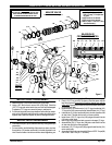
AIR SECTION SERVICE
Service is divided into two parts - 1. Pilot Valve, 2. Major Valve.
GENERAL SERVICE NOTES:
S Air Motor Section Service is continued from step 8 of the Fluid Sec-
tion Disassembly.
S It is not necessary to remove the Fluid Section Ends to gain access
to the Air Motor Major Valve Section.
S In most cases, problems of an air control nature will reside in the Air
Valve area.
S Removal of the Fluid Sections is required to install all of the parts in-
cluded in the Air SectionServiceKit, if this is the case, follow steps 1
thru 8ofthe Fluid S ectionDisassembly on bothsides and isolatethe
Air Section.
S j SERVICE KIT NOTE: Only two replacement “O” rings aresupplied
in the 637338 and 637339-( ) kits.
PILOT VALVE DISASSEMBLY
S
NOTE: Both outer pump Fluid Sections must be removed to access
the Pilot Section parts (see figure 3, page 7).
1. Remove two (123) screws and (104) plate from both sides of the
(101) motor center body.
2. A light tap on (118) actuator pin should expose the opposite (121)
plug and (167) pilot piston.
3. Remove (170) piston sleeve and inspect the inner bore for damage.
PILOT VALVE REASSEMBLY
S
Lubricate all soft parts, spool and bores with Key-Lube grease upon
reassembly.
1. Assemble the trailing (102) “O” ring to (103) sleeve and assemble
sleeve into motor center body, pushing thru far enough to expose
“O” ring groove on opposite end.
2. Assemble (102)“O”ring to (103) sleeveand push sleeve ontomotor
center body.
3. Assemble (2) “O” ring to (1) rod and assemble into (103) sleeve.
4. Assemble (171 and 172) “O” rings to (170) piston sleeve and as-
semble into (101) center body. NOTE: Assemble sleeve with small
i.d. into center body.
5. Assemble two (168) “O” rings and (169) “U” cup to (167) pilot piston
(note the lip direction of “U” cup) and assemble into (170) piston
sleeve.
6. Assemble (173) “O” rings and (174) “U” cups (note lip direction) to
(121) plugs.
7. Assemble (118) actuator pins to (121) plugs and assemble (121)
plugs into (101) center body.
8. Assemble (104) plates to (101) center body, securing with (123)
screws.
9. Reassemble fluid section parts.