


V ``Smart Parts" Keep these items on hand in addition to the Service Kits for fast repair and reduction of down time.
PD30X-XPAGE 6 OF 8
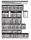
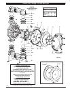
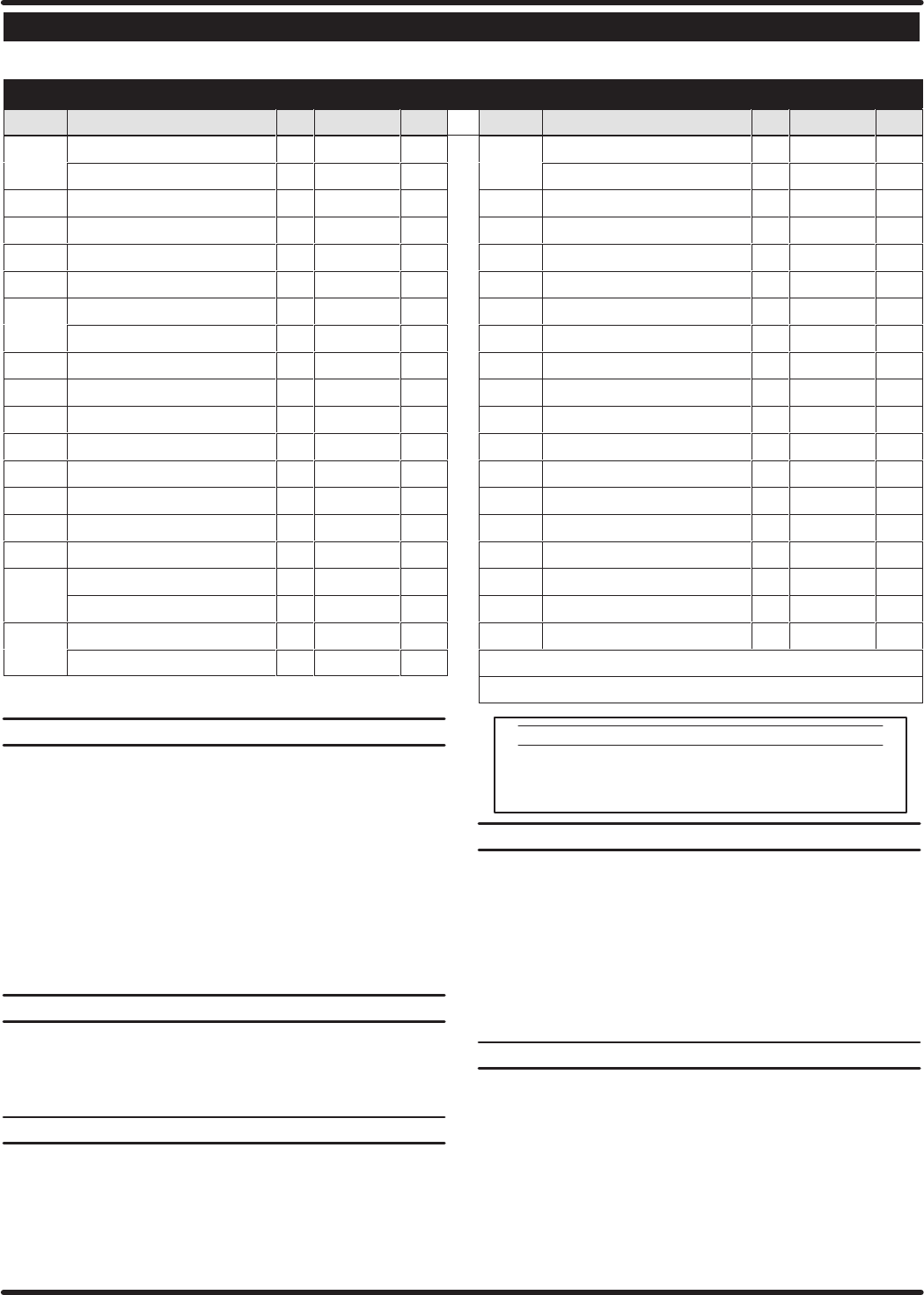
PARTS LIST / PD30X–X AIR SECTION
n Indicates parts included in 637302 Air Section Service Kit shown below and items (70), (144), (175) and (180) shown on page 4.
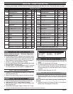
AIR MOTOR PARTS
ITEM DESCRIPTION (Size in Inches) QTY PART NO. [MTL] ITEM DESCRIPTION (Size In Inches) QTY PART NO. [MTL]
101 Center Body(PD30A- ) (1) 94028 [A]
Center Body(PD30S- ) (1) 94109 [SS]
103 Bushing (1) 94092 [D]
107 InletPlug (1) 94034 [C]
109 Piston (1) 92011 [D]
n 110 ``U" Cup (1-3/8" o.d.) (Also Item #144) (1) Y186-51 [B]
111 Spool(PD30A- ) (1) 92005 [A]
Spool(PD30S- ) (1) 93047 [C]
112 Washer (1.556" o.d.) (5) 92877 [Z]
n 113 ``O" Ring (small) (1/8" x 1-1/4" o.d.) (5) Y325-214 [B]
n 114 ``O" Ring (large) (3/32" x 1-9/16" o.d.) (7) Y325-126 [B]
V 115 Spacer (4) 92876 [Z]
116 Spacer (1) 94027 [A]
118 Actuator Pin (.250"x 2.276") (2) 94083 [SS]
121 Sleeve (2) 94084 [D]
n 132 Gasket (Valve Body) (1) 94099 [B]
133 Lockwasher (1/4") (PD30A- ) (3) Y117-416-C [C]
Lockwasher (1/4") (PD30S- ) (3) Y14-416-T [SS]
134 Screw (M6 x 1.0 x 16 mm) (PD30A- ) (4) 96721030 [C]
Screw (M6 x 1.0 x 16 mm) (PD30S- ) (4) 96720081 [SS]
135 ValveBlock (PD30A- ) (1) 94032 [A]
ValveBlock (PD30S- ) (1) 94318 [SS]
136 PistonPlug (1) 94033 [D]
n 146 ``O"Ring z (3/32" x 1-1/16" o.d.) (1) Y325-118 [B]
n 147 ``O" Ring z (1/8" x 1/2" o.d.) Also #174 (2) Y325-202 [B]
n 166 Track Gasket D (1) 94026 [B]
n 167 Pilot Piston(includes 168 and 169) (1) 67164 [D]
168 ``O" Ring (3/32" x 5/8" o.d.) (2) 94433 [U]
169 ``U" Cup (1/8" x 7/8" o.d.) (1) Y240-9 [B]
170 PistonSleeve (1) 94081 [Br]
n 171 ``O"Ring (3/32" x 1-1/8" o.d.) (1) Y325-119 [B]
n 172 ``O"Ring (1/16" x 1-1/8" o.d.) (1) Y325-22 [B]
n 173 ``O"Ring (1/16" x 1-3/8" o.d.) (2) Y325-26 [B]
Ln174 ``O" Ring (1/8" x 1/2" o.d.) (2) Y325-202 [B]
n 176 Diaphragm (Check Valve) (2) 94102 [U]
n 177 Retaining Ring(1.804" dia.) (1) Y147-16-C [C]
181 Roll Pin z (.156" o.d. x 3/4" long) (4) Y178-56-S [SS]
LĂn Lubriplate FML-2 Grease (1) 94276
Lubriplate Grease Packets (10) 637308
z UsedonStainless Steelmodels (PD30S-) only.
D Used on Aluminummodels (PD30A- ) only.
AIR MOT
OR SECTION SER
VICE
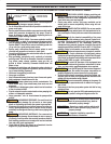
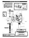
Service is divided into two parts - 1.Pilot Valve, 2.Major Valve.
GENERALREASSEMBLYNOTES:
S Air Motor Section Service is continued from Fluid Section repair.
S Inspect and replace old partswith new parts asnecessary. Look for
deep scratches on metallic surfaces, and nicks or cuts in ``O" rings.
S Take precautions to prevent cutting ``O" rings upon installation.
S Lubricate ``O" rings with Lubriplate FML-2 Grease.
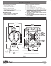
S Do not over-tighten fasteners, refer to torque specification block on view.
S Re-torque fasteners following restart.
S SERVICE TOOLS- To aidin the installationof (168) ``O'' rings onto
the (167) pilot piston, use Tool # 204130-T, available from Aro.
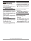
PILOT
V
AL
VE DISASSEMBL
Y
1. A light tap on (118) should expose the opposite (121) sleeve, (167)
pilot piston and other parts.
2. Remove (170) sleeve, inspect inner bore of sleeve for damage.
PILOT
V
AL
VE REASSEMBL
Y
1. Clean and lubricate parts not being replaced from service kit.
2. Install new (171), (172) ``O" rings, replace (170) sleeve.
3. Install new (168)``O" rings, (169) seal - Note the lip direction. LubriĆ
cate and replace (167).
4. Reassemble remaining parts, replace (173) and (174) ``O" rings.
MATERIAL CODE
[A] = Aluminum [CI] = Cast Iron [SS] = StainlessSteel
[B] = Buna``N" [D] = Acetal [U] = Polyurethane
[Br] = Brass [SP] = Santoprene [Z] = Zinc
[C] = CarbonSteel
MAJOR
V
AL
VE DISASSEMBL
Y
1. Remove (135) valve block exposing gaskets (166), (132)and (176)
checks.
2. Remove (177) snap ring and (107) inlet plug.
3. On the side opposite the air inlet, push on the inner diameter (111)
spool. This will force the (136) piston plug and (109) piston out.
Continue pushing the (111) spool and remove. Check for scratches
or gouges.
4. Remove the Major Valve parts (112-116).
MAJOR
V
AL
VE REASSEMBL
Y
1. Replace (112) washer, (114) ``O" ring, (113) ``O" ring onto (115)
spacer and insert etc. Continue this routine to build the major valve
stack.
NOTE: Be careful to orient spacer legs away from blocking interĆ
nal ports.
2. Replace (111) spool on (136) plug, (110) seal on (109) piston and
replace (109), (136) plug and (177) snap ring.