


PAGE 3 OF 8PD30X-X
AIR
AND LUBE REQUIREMENTS
WARNING EXCESSIVE AIR PRESSURE. Can cause pump
damage, personal injury or property damage.
S A filter capable of filtering out particles larger than 50 microns
should be used on the air supply. In most applications there is no
lubrication required other than the ``O" ring lubricant which is apĆ
plied during assembly or repair.
S When lubricated air is necessary, supply the air lubricator with a
goodgrade of SAE 90 wt.non-detergent oil andsetthelubricator to
a rate not to exceed one drop per minute.
OPERATING INSTRUCTIONS
S Always flush the pump with a solvent compatible with the material
being pumped if the material being pumped is subject to ``setting
up" when not in use for a period of time.
S Disconnect the air supply from the pump if it is to be inactive for a
few hours.
S The outlet material volume is governed not only by the air supply
but also by the material supply available at the inlet. The material
supply tubing should not be too small or restrictive. Be sure not to
use hose which might collapse.
S When the diaphragm pump is used in a forced-feed (flooded inlet)
situation it is recommended that a ``Check Valve" be installed at the
air inlet.
S Secure the diaphragm pump legs to a suitable surface to insure
against damage by vibration.
MAINTENANCE
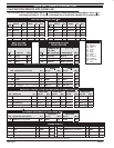
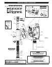
Refer to the part views and descriptions asprovided on page 4 through
7 for parts identification and Service Kit information.
S Certain ARO``SmartParts" areindicated which shouldbe available
for fast repair and reduction of down time.
S Service kits are divided to service two separate diaphragm pump
functions: 1. AIR SECTION,2. FLUID SECTION. The FLUIDSECĆ
TION is dividedfurther to match typical partMATERIAL OPTIONS.
MAINTENANCE (CONT’D)
S Provide a clean work surface to protect sensitive internal moving
parts from contamination from dirt and foreign matter during serĆ
vice disassembly and reassembly.
S Keep good records of service activity and include pump in prevenĆ
tive maintenance program.
S Before disassembling empty captured material in the outlet manĆ
ifold by turning the pump upside down to drain material from the
pump.
FLUID
SECTION DISASSEMBL
Y
1. Remove top manifold(s).
2. Remove (22) balls, (19) ``O" rings and (21) seats.
3. Remove (15) fluid caps.
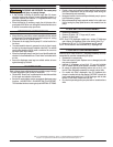
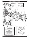
NOTE: Only diaphragm models use a primary (7) diaphragm
and a backup (8) diaphragm. Refer to the auxiliary view. Fig.1
4. Remove the (6) nut, (7) or (7/8) diaphragms and (5) washer.
NOTE: Do not scratch or mar the surface of (1) diaphragm rod.
FLUID
SECTION REASSEMBL
Y
SERVICE NOTE: ARO PN 204214-T Diaphragm Assembly Tool isrecĆ
ommended for use when reassembling the pump.
S Reassemble in reverse order.
S Clean and inspect all parts. Replace worn or damaged parts with
new parts as required.
S Lubricate (1) diaphragm rod and (144) ``U" cup with Lubriplate
FML-2 Grease. (94276 grease packet is included in service kit.)
S Be certain the diaphragm assembly bottoms out on the (1) rod,
back off Teflon Diaphragm assembly far enough to align holes.
S For models with Teflon diaphragms: Item (8) Santoprene diaĆ
phragm is installed with the side marked ``AIR SIDE" towards the
pump center body. Install the (7) Diaphragm with the side
marked ``FLUID SIDE" towards the fluid cap.
S Re-check torquesettings after pump hasbeenre-startedandrun a
while.
KynarRisaregisteredtrademarkofPenwaltCorp.SGeolastRisaregisteredtrademarkofAdvancedElastomerSystems
SantopreneRisaregisteredtrademarkofMonsantoCompany,licensedtoAdvancedElastomerSystems,L.P.
PTFE
PTFE