


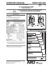
Page 6 of 8 PD05P-XXX-XXX (en)
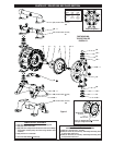
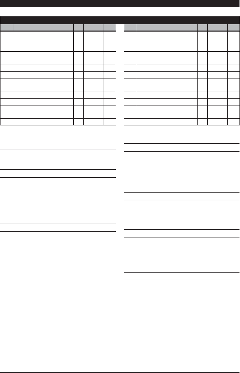
PARTS LIST / PD05P-XXX-XXX AIR MOTOR SECTION
9
Indicates parts included in 637141 air section repair kit.
MATERIAL CODE
[B] = Nitrile [D] = Acetal [SY] = Syn-Seal
[Bz] = Bronze [P] = Polypropylene [U] = Polyurethane
[C] = Carbon Steel [PS] = Polyester [Z] = Zinc
[Ck] = Ceramic [SS] = Stainless Steel
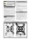
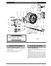
DIAPHRAGM PUMP SERVICE
GENERAL SERVICE NOTES:
Inspect and replace old parts with new parts as neces-
sary. Look for deep scratches on metallic surfaces, and
nicks or cuts in “O” rings.
Tools needed to complete disassembly and repair:
1/2” socket or wrench, 7/16” socket or wrench, torque
wrench (measuring inch pounds), “O” ring pick.
FLUID SECTION DISASSEMBLY
Remove (61) top manifold.
Remove (19) “O” rings, (21) seats, (12) washers (where ap-
plicable) and (22) balls.
Remove (60) bottom manifold.
Remove (19) “O” rings, (21) seats, (12) washers (where ap-
plicable) and (22) balls.
Remove (15) uid caps.
Remove (14) bolt, (6) diaphragm washer, (7) or (7 / 8) dia-
phragms and (5) washer.
Remove (1) connecting rod from air motor.
Carefully remove remaining (14) bolt, (6) diaphragm
washer, (7) or (7 / 8) diaphragms and (5) washer from (1)
connecting rod. Do not mar surface of connecting rod.
Remove (2) “O” ring from connecting rod.
y
y
y
1.
2.
3.
4.
5.
6.
7.
8.
9
.
FLUID SECTION REASSEMBLY
Reassemble in reverse order.
Lubricate (1) connecting rod and (2) “O” ring with Key-
Lube “O” ring lube.
Install (5) washers with i.d. chamfer toward diaphragm.
When replacing PTFE diaphragms, install the 93465 San-
toprene diaphragm behind the PTFE diaphragm.
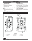
AIR MOTOR SECTION SERVICE
Service is divided into two parts - 1. Pilot Valve, 2. Major
Valve.
Air Motor Section service is continued from Fluid Section
repair.
PILOT VALVE DISASSEMBLY
Remove (122 and 104) snap rings.
Remove (143) plates.
Remove (103) sleeve and (102) “O” rings.
Remove (118) piston, (142) washers, (119) “O” rings and
(120) spacers from (101) motor body.
PILOT VALVE REASSEMBLY
Assemble (119) "O" rings, (120) spacers and (142) washers
on (118) piston.
Insert the stack into the (101) body. (103) sleeve may be
used to assist pressing stack into body.
Install (103) sleeve and (102) "O" rings into (101) body.
Install (143) plates and (122 and 104) snap rings.
y
y
y
y
y
1.
2.
3.
4.
1.
2.
3.
4
.
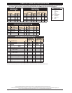
AIR MOTOR PARTS LIST
Item Description
(size)
(Qty) Part No. [Mtl] Item Description
(size)
(Qty) Part No. [Mtl]
101 Motor Body (1) 93091 [P]
9
102 “O” Ring
(3/32” x 1” o.d.)
(2) Y325-117 [B]
103 Sleeve (1) 93087 [Bz]
104 Snap Ring
(13/16”)
(2) 37285 [C]
111 Spool (1) 93085 [D]
118 Piston (1) 93088 [C]
9
119 “O” Ring
(1/8” x 3/4” o.d.)
(4) 93075 [U]
120 Spacer (3) 115959 [Z]
9
122 Snap Ring
(1/2”)
(2) 77802 [C]
129 Mu er (1) 66972 [P]
129 Exhaust Cover
(optional)
(1) 93092 [PS]
9
130 Gasket (1) 93107 [SY]
131 Bolt
(5/16 - 18 x 1-1/4”)
(16) 93095 [SS]
9
132 Gasket (1) 93339-1 [B]
133 Washer
(9/32” i.d.)
(4) 93096 [SS]
134 Bolt
(1/4” - 20 x 5”)
(4) Y6-419-T [SS]
135 Valve Block (1) 93090 [P]
136 Plug (1) 93086 [D]
9
137 “O” Ring
(3/32” x 1-1/2” o.d.)
(1) Y325-125 [B]
9
138 “U” Cup Packing
(1/8” x 1” o.d.)
(1) 94395 [U]
9
139 “U” Cup Packing
(1/8” x 1-7/16” o.d.)
(1) 96383 [U]
9
140 Valve Insert (1) 93276 [Ck]
9
141 Valve Plate (1) 93275 [Ck]
142 Washer (2) 116038 [Z]
143 Plate (2) 93089 [SS]
201 Mu er
(optional)
(1) 93110 [C]
9
Key-Lube, “O” Ring Lubricant (1) 93706-1
Key-Lube, 10 Pack 637175
“Smart Parts”, keep these items on hand in addition to the service kit for
fast repair and reduction of down time.
NOTE 1: A major valve service assembly is available separately which in-
cludes items 111, 132, 135 - 141. Order part number 66362.