


75.5255.02 XXXXXXXX
7940-8770 LCN Page 3 of 11
ELECTRICAL
INSTALLATION
AND CABLING
MECHANICAL
INSTALLATION
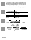
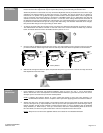
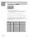
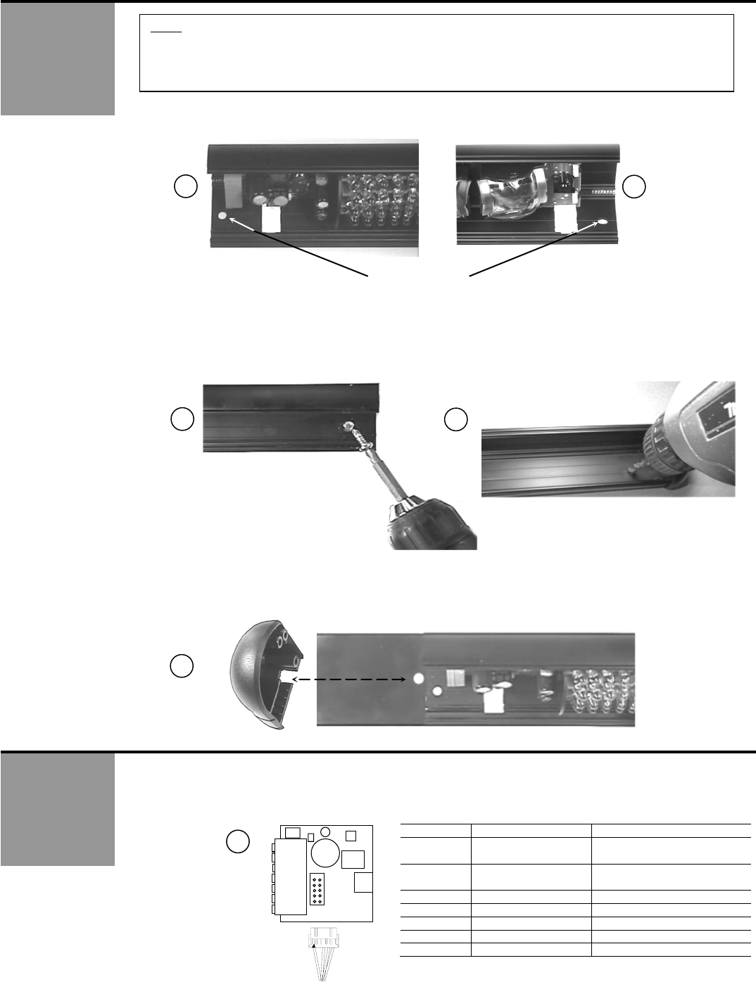
1. The extrusion has pre-drilled mounting holes at each end as shown below in pictures 5 & 6.
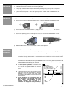
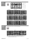
2. Hold the Presence Sensor up to the pre-determined location, and attach using the 2 self-drilling screws
that are included with the package, as shown in picture 7 below. It may be necessary to pre-drill a pilot
hole (picture 8) in the header for ease of screw installation. Ensure that Presence Sensor is mounted
securely at each end.
3. If Presence Sensor is mounted directly to door header, and cabling is to pass directly into header, drill a ¼”
hole next to the Presence Sensor’s left side end cap to allow wire passage into header as shown below.
The wire passage hole should be in a location that aligns with the cut out in the end cap as shown below.
Once the Presence Sensor is securely attached to header, cabling & wiring may be completed.
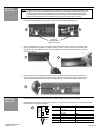
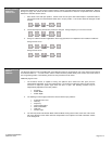
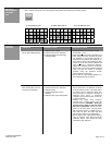
1. Install the 10-pin connector as shown below in picture 10. If wiring the Presence Sensor to a LCN module, refer to
the schematic for the respective module.
Position Connection 7-Pin Wire Color (10-pin cable)
1 12 to 24 V AC / DC
+/- 10%
Red
2 24 to 24 V AC / DC
+/- 10%
Black
3 Common White
4 Normally Open Green
5 Normally Closed
6 Data - Brown
7 Data + Blue
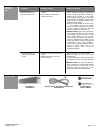
NOTE: LCN recommends the use of a BodyMount P/N 761222-79 for most Presence Sensor applications. The
BodyMount is a 3” standoff that allows the Presence Sensor to be slightly distanced from the face of the
closed door. This helps to prevent ghosting caused by slight door movement while closed, and also
prevents ghosting when Door Mounted Safety Sensors are used (as the Door Mounted Safety Sensor
extrusions at the top of the door are extremely close to the sensor while the door is closed).
Pre Drilled
Mounting Holes
A
pp
rox. 9 ¾” A
p
art
5
6
7
8
9
10
1 PWR
2 PWR
3 COM
4 NO
5 NC
6 IN -
7 IN +
10 PIN
10 PIN