


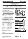
Page 6 of 8 66610X-X-C (en)66610X-X-C (en)
“Smart Parts” Keep these items on hand in addition to the Service Kits for fast repair and reduction of down time.
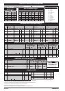
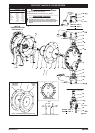
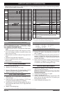
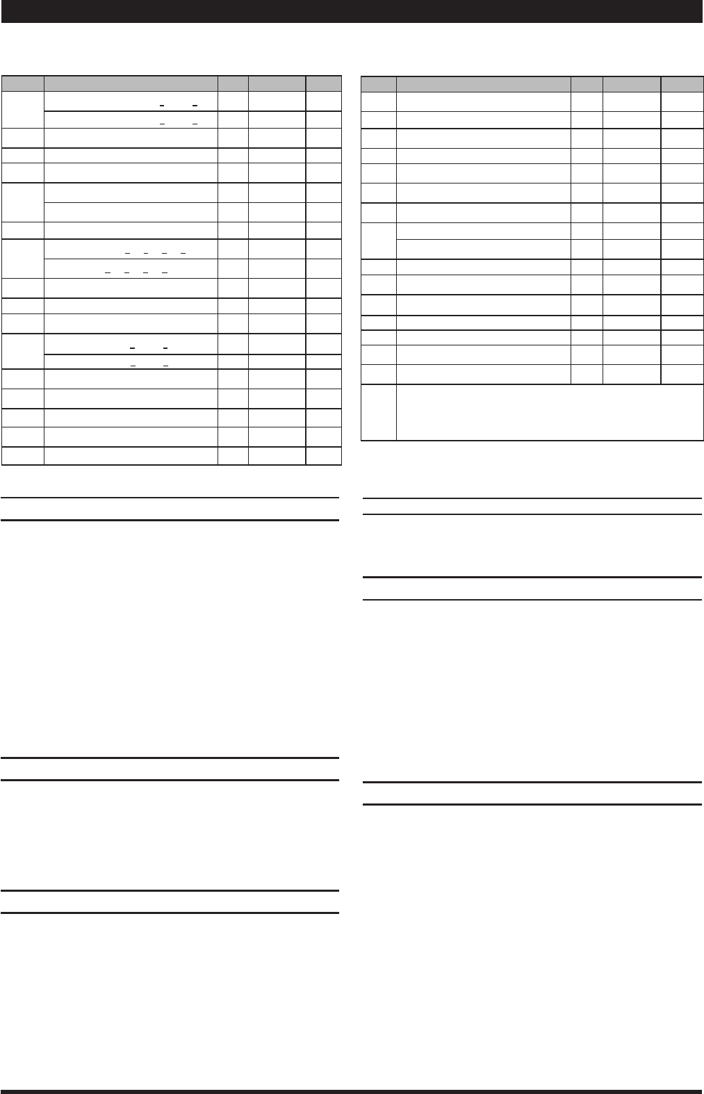
PARTS LIST / 66610X-X-C AIR MOTOR SECTION
Indicates parts included in 637118-C Air Section Service Kit.
SERVICE KIT NOTE: Service Kit 637118-C is a general repair kit for all 1” and larger ARO diaphragm pump air motors. It contains extra “O” Rings and other-
parts that may not be needed to service this model.
Item Description
(size)
Qty Part No. [Mtl]
101
Motor Body
(models 66610X, 66612X)
(1) 94743 [A]
(models 66611X, 66612X)
(1) 94741 [CI]
102 “O” Ring
(1/16” x 1” o.d.)
(2) Y325-20 [B]
103 Sleeve (1) 94527 [D]
104 Retaining Ring, TruArc
(.925” i.d.)
(2) Y145-25 [C]
105
Screw/Wshr
(1/4”-20 x 5/8”) (-XX0, 1, 2, 9)
(8) 93860 [C]
Cap Screw
(1/4”-20 x 5/8”) (-XXA, B, C, D)
(8) Y6-42-T [SS]
106 Lockwasher
(1/4”)
(8) Y14-416-T [SS]
107
Leg
(models 6661X0, 1X1, 1X2, 1X9)
(2) 92003 [C]
(models 6661XA, 1XB, 1XC, 1XD)
(2) 92003-1 [SS]
108 Gasket (with notch) (1) 92878 [B/Ny]
109 Piston (1) 92011 [D]
110 “U” Cup
(3/16” x 1-3/8” o.d.)
(1) Y186-51 [B]
111
Spool
(models 66610X, 66612X)
(1) 92005 [A]
(models 66611X, 66613X)
(1) 93047 [C]
112 Washer
(1.557” o.d.)
(5) 92877 [Z]
113 “O” Ring
(1/8” x 1-1/4” o.d.)
(5) Y325-214 [B]
114 “O” Ring
(3/32” x 1-9/16” o.d.)
(6) Y325-126
[B]
115 Spacer (4) 92876
[Z]
116 Spacer (1) 92006 [Z]
AIR MOTOR SECTION SERVICE
Service is divided into two parts − 1. Pilot Valve, 2. Major
Valve. GENERAL REASSEMBLY NOTES:
Air Motor Section Service is continued from Fluid Section
repair.
Inspect and replace old parts with new parts as neces-
sary. Look for deep scratches on metallic surfaces, and
nicks or cuts in “O” rings.
Take precautions to prevent cutting “O” rings upon instal-
lation.
Lubricate “O” rings with Key-Lube grease.
Do not overtighten fasteners, refer to torque specication
block on view.
Re-torque fasteners following restart.
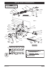
PILOT VALVE DISASSEMBLY
Remove (104) retaining ring.
Remove (123) screws and (122) “O” rings.
1.
2.
Remove (118) piston rod, (121) sleeve bushing, (119) “O”
rings and (120) spacers from the (101) motor body.
Remove (103) sleeve and (102) “O” rings.
3.
4.
PILOT VALVE REASSEMBLY
Replace two (102) “O” rings if worn or damaged and rein-
stall (103) sleeve.
Install one of the (121) sleeve bushings, (119) “O” rings,
(120) spacers and the remaining (121) bushing.
Carefully push (118) pilot rod into bushings etc. and re-
tain on each end with the two (122) “O” rings, retain with
(123) screws.
Replace (104) retaining rings.
1.
2.
3.
4.
Parts Y 145-26 (1.156" i.d.) (qty 2) retaining rings and Y325-24 "O" rings (qty 2)
are included in the service Kit for te=he repair of larger pumps.
Item Description
(size)
Qty Part No. [Mtl]
117 Gasket (1) 92004 [B/Ny]
118 Pilot Rod (1) 93309-1 [C]
119 “O” Ring
(1/8” x 3/4” o.d.)
(4) 93075 [U]
120 Spacer (3) 115959 [Z]
121 Sleeve Bushing (2) 98723-1 [Bz]
122 “O” Ring
(3/32” x 9/16” o.d.)
(2) 94820 [U]
123 Screw
(#8 - 32 x 3/8”)
(4) Y154-41 [C]
124
Stud
(5/16” - 18 x 1-3/4”) (6661X0, 1X1, 1X2
,
1X9)
(16) 92866 [C]
(5/16” - 18 x 1-3/4”) (6661XA, 1XB, 1XC, 1XD)
(16) 92866-1 [SS]
128 Pipe Plug
(1/8 - 27 N.P.T. x 1/4”)
(1) Y227-2-L [C]
133
Lockwasher
(1/4”)
(1)
Y14-416-T
[SS]
197 Button Head Screw
(1/4” - 20 x 1/4”)
(3) 94987 [SS]
198 Button Head Screw
(1/4” - 20 x 3/8
”) (1) 94987-1 [SS]
201 Muer (1) 93110 [C]
Key-Lube “O” Ring Lubricant (1) 93706-1
Pak of 10 Key-Lube 637175
Service Kits include: Y212-101 (2) Screws (#10 - 32 x 1/4”)
used on units manufactured between 8/90 and 4/92 to retain
the pilot bushing.
MATERIAL CODE
[A] = Aluminum [CI] = Cast Iron [SS] = Stainless Steel
[B] = Nitrile [D] = Acetal [U] = Polyurethane
[Bz] = Bronze [N] = Neoprene [Z] = Zinc
[C] = Carbon Steel [NY] = Nylon
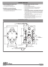
MAJOR VALVE DISASSEMBLY
Remove (107) plate (or leg depending on model), (108
and 117) gaskets.
On the side opposite the air inlet, push on the inner di-
ameter (111) spool. This will force the (109) piston out.
Continue pushing the (111) spool and remove. Check for
scratches and gouges.
Reach into the air section (exhaust side) and remove
(116) spacer, (115) spacers, (113) “O” rings, (114) “O” rings,
(112) washers, etc. Check for damaged “O” rings.
1.
2.
3.
MAJOR VALVE REASSEMBLY
Replace (112) washer, (114) “O” ring and (113) “O” ring
onto (115) spacer and insert etc.
NOTE: Be careful to orient spacer legs away from
blocking internal ports.
2. Lubricate and carefully insert (111) spool.
3. Install (117) gasket and (107).
4. Lubricate and install (110) packing cup and insert (109)
piston into (air inlet side) cavity, the (110) packing cup
lips should point outward.
5. Install (108) gasket and replace (107).
1.