


66610X-X-C (en) Page 3 of 8 Page 3 of 8
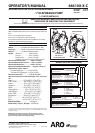
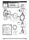
GENERAL DESCRIPTION
The ARO diaphragm pump oers high volume delivery even at
low air pressure and a broad range of material compatibility op-
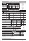
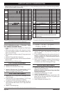
tions available. Refer to the model and option chart. ARO pumps
feature stall resistant design, modular air motor / uid sections.
Air operated double diaphragm pumps utilize a pressure dif-
ferential in the air chambers to alternately create suction and
positive uid pressure in the uid chambers, valve checks insure
a positive flow of fluid. Pump cycling will begin as air pressure
is applied and it will continue to pump and keep up with the
demand. It will build and maintain line pressure and will stop cy-
cling once maximum line pressure is reached (dispensing device
closed) and will resume pumping as needed
.
AIR AND LUBE REQUIREMENTS
WARNING
EXCESSIVE AIR PRESSURE. Can cause
personal
injury, pump damage or property damage.
A filter capable of filtering out particles larger than 50 mi-
crons should be used on the air supply. There is no lubrication
required other than the “O” ring lubricant which is applied
during assembly or repair.
If lubricated air is present,makesure that it is compatible
with the “O” rings and seals in the air motor section of the
pump.
OPERATING INSTRUCTIONS
Always flush the pump with a solvent compatible with
the material being pumped if the material being pumped
is subject to “setting up” when not in use for a period of
time.
Disconnect the air supply from the pump if it is to be in-
active for a few hours.
The outlet material volume is governed not only by the
air supply, but also by the material supply available at the
inlet. The material supply tubing should not be too small
or restrictive. Be sure not to use hose which might co
lapse.
When the diaphragm pump is used in a forced-feed
(ooded inlet) situation, it is recommended that a “Check
Valve” be installed at the air inlet.
Secure the diaphragm pump legs to a suitable surface to
insure against damage by vibration.
MAINTENANCE
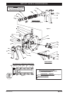
Refer to the part views and descriptions as provided on pages
4 through 7 for parts identication and service kit information.
Certain ARO “Smart Parts” are indicated which should be
available for fast repair and reduction of down time.
Service kits are divided to service two separate dia-
phragm pump functions: 1. AIR SECTION, 2. FLUID SEC-
TION. The FLUID SECTION is divided further to match
typical part MATERIAL OPTIONS.
Provide a clean work surface to protect sensitive internal
moving parts from contamination from dirt and foreign
matter during service disassembly and reassembly.
Keep good records of service activity and include pump
in preventive maintenance program.
Before disassembling, empty captured material in the
outlet manifold by turning the pump upside down to
drain material from the pump.
FLUID SECTION DISASSEMBLY
Remove top manifold(s).
Remove (22) balls, (19) “O” rings and (21) seats.
Remove (15) uid caps.
NOTE: Only PTFE diaphragm models use a primary dia-
phragm (7) and a backup diaphragm (8). Refer to the auxil-
iary view in the Fluid Section
illustration.
For 6661XX-XX6-C:
4. Remove (7)diaphragm,(5)washers and (30)shims.
For other models:
4. Remove the (14) screws, (6) washers, (7) or (7 / 8) dia-
phragms and (5) washers.
5. Remove (3) “O” rings.
1.
2.
3.
Viton
®
and Hytrel
®
are registered trademarks of the DuPont
®
Company. Kynar
®
is a registered trademark of Penwell Corp
Santoprene
®
is a registered trademark of Monsanto Company, licensed to Advanced Elastomer Systems, L.P. Key-Lube
®
is a registered trademark of Key Industries
FLUID SECTION REASSEMBLY
Reassemble in reverse order.
Clean and inspect all parts. Replace worn or damaged
parts with new parts as required.
Lubricate (1) diaphragm rod and (2) “O” ring with Key-
Lube “O” ring lube.
Use ARO pn / 98931-T bullet (installation tool) to aid in
installation of (2) “O” ring on (1) diaphragm rod.
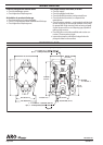
For 6661XX-XX6-C:
Attach a regulated airline to the pump inlet; gradually
increasing the air pressure (6-8 psi) to check which side of
the pump with air blowing out, and then shut down the
air supplier.
Fasten (7) diaphragm with (5) washer into (1) diaphragm
rod, and insert them into (101) Center body from the
chamber identied with blowing air in the previous step.
Install (15) uid cap.
Thread the other side of (7) diaphragm with (5) washer
into (1) diaphragm rod, but do not tighten it.
Record the angle for the misalignment between (7) dia-
phragm hole and (101) center body holes, then unthread
the (7) diaphragm and place proper Qty. of (30) shims
between (5) washer and (1) diaphragm rod.
Attach a regulated airline to the pump inlet, gradually
increasing the air pressure (6-8 psi) until the diaphragm
shift to the other site, shut down the air supply.
Install the second (15) uid cap.
Note: for details, refer to service kits manual 48495949.
For other models:
Be certain (7) or (7 / 8) diaphragm(s) align properly with
(15) uid caps before making nal torque adjustments on
bolt and nuts to avoid twisting the diaphragm.
For models with PTFE diaphragms: Item (8) Santoprene
diaphragm is installed with the side marked “AIR SIDE” to-
wards the pump center body. Install the PTFE diaphragm
with the side marked “FLUID SIDE” towards the uid cap.
Re-check torque settings after pump has been re-started
and run a while.