


PAGE 5 OF 8
651616-X
OPERATING INSTRUCTIONS
OPERATING INSTRUCTIONS / INITIAL SETUP PROCEDURE
WARNING
STANDCLEAR. Whenraisingor loweringthe lift.
Read the warning on page 2.
TO RAISE LIFT, (THE FIRST TIME):
1. Take note of the pump /drum clearance above. Be certain the lift is
clearofanyobjectsabove.AlsorefertoOPERATINGANDSAFETY
PRECAUTIONS found on page 2.
2. Connecttheairsupply(150p.s.i./10.3barmaximum)totheairinlet.
3. Shift the control valve lever to the ‘‘UP’’ position.
4. Raisethelift highenoughtocleartheheight ofthedrum.Stop thelift
upward travel by moving the control valve lever to the (center)
‘‘NEUTRAL’’ position.
TO RAISE LIFT, (NORMAL OPERATION):
1. Adjust the follower plate air valve pressure. DO NO OVERPRES-
SURIZE THE DRUM to avoid damage.
NOTE: Air from this valve will only pass when the control lever is in
the ‘‘UP’’ position.
2. Shift the control valve lever to the ‘‘UP’’ position.
3. Raisethelift highenoughtocleartheheight ofthedrum.Stop thelift
upward travel by moving the control valve lever to the (center)
‘‘NEUTRAL’’ position.
TO CHANGE DRUMS:
NOTE: The control lever should be in the ‘‘NEUTRAL’’ position.
1. Place a new drum into position.
TO LOWER LIFT:
WARNING
PINCH HAZARD. Follower can descend quickly
causinginjury.Keephandsclearwhenaligningwithcontainer.
Read the warning on page 2.
NOTE:Be certainthefollowerplate ventplughasbeenremoved sothat
the air trapped between the follower and the material is allowed to es-
cape from this vent. Captured air between the follower plate and drum
will escape.
NOTE:The liftmay hesitatemomentarilybefore starting downward,the
air pressureinside thepost airchamber mustdecrease beforeit willbe-
gin to descend.
1. Shift the control valve leverto the ‘‘DOWN’’ positionand proceedto
lower the pump.
2. Replacetheventplugoncethematerialbeginstooozefromthevent
opening.
DISASSEMBLY
1. Remove the top cross support bar from the cylinder pistons.
2. Remove the air valve assembly from the r ight post.
The following piston removal instructions are the same for both sides.
Piston removal requires the following tools:
S Screwdriver (flat blade)
S .400” diameter rod, 12” - 18” long
S E - Ring pliers
3. Using the E - ring pliers, remove the snap ring which retains the
backup washer and upper piston ‘‘U” cup seal.
4. Locate one of the two service holes in the cap and insert the .400”
diameter rod.
5. Locate the end of the square retaining wire found 1”down from the
top of the cylinder.
6. Thebent tipofthewire protrudesslightly. Usinga screwdriver,care-
fully pryoutthe wireslightly whileusing therod to rotatethe capina
clockwise direction360_. Unwindthe wire andexpose the endwith
the 90_ bend.
7. Remove the wire from the machined hole.
8. Remove the cap from the cylinder and remove from the piston, re-
move the washer and upper seal.
9. Remove the piston assembly. Disassemble as required to replace
worn seals.
REASSEMBLY
1. Thoroughlylubricate thecylinder wall,all sealsand especiallylubri-
cate the groove where the retaining wire is located to aid in reas-
sembly.
2. Replace the cap, align the hole with the access slot. Place the 90_
bendofthe wire intothe machinedholeandsnapinplace.Usingthe
.400” diameter rod, rotate the cap clockwise and feed the retaining
wire into position.
3. Placethenew seal(withlipsdown) onthepiston,reinstallthe wash-
er, place a sleeve over the piston rod to help ‘‘seat” the upper seal.
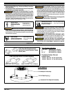
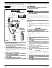
PRESSURE
REGULATOR
FOLLOWER PLATE
AIR SUPPLY VALVE
CONTROL
LEVER
GAUGE
AIR CONTROLS
FIGURE 4
OFF
ON