


651616-XPAGE 4 OF 8
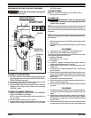
LIFT / RAM INSTALLATION
WARNING
Failuretoproperlyinstalltheliftassemblycanre-
sult in severe personal injury and property damage. Read the
warning on page 2.
1. This assemblyis shipped in twocartons: a) the followerplate b) the
ram / lift. Assemble the vertical rods to the Horizontal Bracket to
match the pump and follower plate combination.
2. Establishthe desiredlocation forthe lift/ram andpay specialatten-
tion to workarea above, this areaabove the lift must beopen, with-
out obstructions and safely away from any electrical devices.
3. THE LIFT MOUNTING PLATE BASE MUST BE SECURELY AN-
CHORED TO THE CONCRETE FLOOR.The mounting plate itself
can be used for a template for establishing the proper anchor loca-
tions.
4. Placethe pumponthe followerplate andalignthepump andfollow-
er plate on the base and assemble the appropriate vertical rods.
5. Install the check and follower plate air hose from the control valve.
6. Assemble the vent plug to the follower plate.
7. When large pump motors are used, the horizontal arm should be
turned overto accommodatethe F-R-Lwhich canthen be mounted
on top.
NOTE: The ram was tested at the factory. The unit should be generally
checked overforleakage, because the fittingson the systemmay have
loosened in shipment.
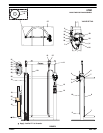
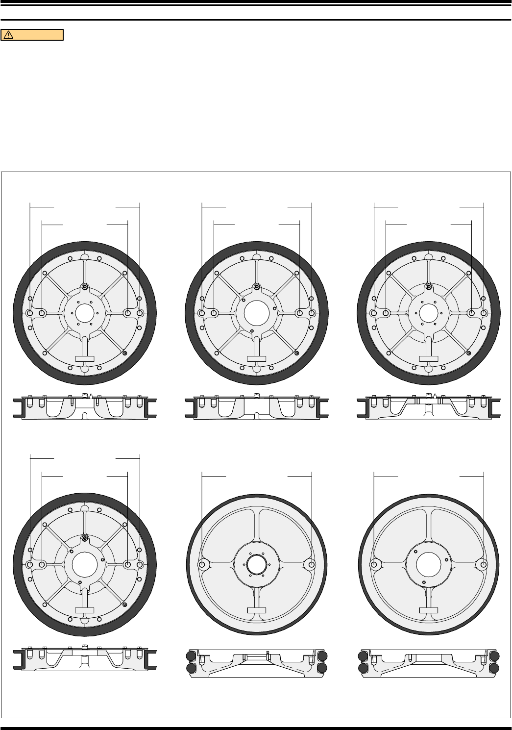
67196-X
66667-X66517-X
66668-X
66516-X
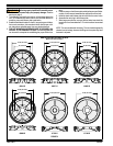
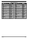
ARO 55 GALLON FOLLOWER PLATES
17-7/8’’ (454.0mm)
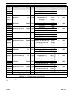
(Refer to the chart on page 3)
67195-X
14’’ (355.6 mm)
17-7/8’’ (454.0mm)
14’’ (355.6 mm)
17-7/8’’ (454.0mm)
14’’ (355.6 mm)
17-7/8’’ (454.0mm)
14’’ (355.6 mm) 17-7/8’’ (454.0mm) 17-7/8’’ (454.0mm)
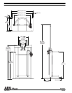
FIGURE 3