


Page2of4 650453-X
• Disconnect air line from pump air motor when system sits idle for
long periods of time.
• Materialsandsolventsbeingpumpedbythispumpmust becompat-
iblewith thepartsof thispumpthat comeincontact with the material
and solvent.
• SERVICING. Before servicing or cleaning pump, or removing fluid
hoseor gunfromaunit thathas beenused,besureto disconnectair
lines and carefully bleed the pressure off the system.
• WARNING: PREVENT STATIC SPARKING. If static sparking
occurs, fire or explosion could result. Pump, dispensing valve and
containers must be grounded when handling inflammable fluids
such as petroleum products, paints, lacquers, etc. and wherever
discharge of static electricity is a hazard.
• Usegroundedhoses (staticwire)andbe suretheobjectisgrounded
If it can produce a static charge.
• Check continuity (a goodstatic wire connection)with an ohmmeter.
Place one probe on one hose fitting and the other probe on other
hose fitting, continuity or proper grounding through hose is good
when a reading is obtained on the ohmmeter.
• PREVENT FIRES. Whenpumping, flushing or recirculatingvolatile
solvents, the area must be adequately ventilated.
• Keep solventsaway from heat, sparks andopen flames. Keepcon-
tainers closed when not in use.
• CAUTION: Do not allow pump to operate when out of material.
AIR & LUBE REQUIREMENTS
• Excessive air pressure will shorten the life of the pump. DO NOT
OPERATE PUMP ABOVE RECOMMENDED MAXIMUM AIR
PRESSURE.
• Formaximumoperatingefficiency,thefollowingairsupplyspecifica-
tions should be maintained to this pump.
a)
AIR PRESSURE - up to 150 p.s.i. (10.3 bar)
b) AIR FILTRATION - 50 micron
c) LUBRICATED AIR SUPPLY
d) AIR INLET SIZE 1/2 - 14 N.P.T.F.
• Filtered and oiled air will allow the pump to operate more efficiently
and yield a longer life to operating parts and mechanisms.
• Lack of or an excessive amount of lubrication will af fect the perfor-
mance and life of this pump. Use only recommended lubricants.
• DAILY Fill air line lubricator reservoir with a good grade of S.A.E.
NO. 90 W non-detergent gear oil, adjustto 1 to 2 drops per minute.
• If pump is to beinoperative for morethan a few hoursat a time,dis-
connect air supply and relieve all pressure from the system.
• It isrecommendedthat anoiler be installed in theair lineas close as
possible to the pump. Thisincreases the s ervice lifeof the pumpby
reducing wear of the air motor’s internal parts.
INSTALLATION
•
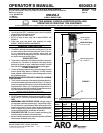
The 650453-5 or -8 pump is to be mounted in the 2” bung of a 55
gallon drum.
• The 650453-7, -9, -10 or -11 pump is to be wall mounted. A 61113
pump mounting bracket may be used to mount pump to wall.
FLUSH PUMP
1. Connect fluid hose to pump outlet. Be sure all fittings are tight.
2. Turn air regulator knob counter-clockwise until it turns free.
3. Pump hasbeen testedinoil anda smallamount remainsfor protec-
tionagainstrusting.Immerselowerpump endincompatiblesolvent.
4. Connect air hose coupler to connector on Filter - Regulator - Lubri-
cator.
5. Turn air regulator knob clockwise until air motor starts. Flush pump
until oil is removed.
6. Disconnect air supply to air motor.
• CAUTION: Solvent used for flushing may not be compatible with
material tobe pumped.If thisisthe case,flush againwith acompat-
ible solvent.
• Ifpump isto bei noperativeforan unspecifiedperiodoftime, discon-
nect air and relieve all pressure.
• If pump does not function properly, disconnect air and relieve all
pressure. Refer to “Trouble Shooting”.
OPERATING INSTRUCTIONS
1. Turn air regulator knob clockwise until air motor starts to cycle.
2. Allow pumptocycle slowly untilitis primedand allairis purgedfrom
the fluid hoseor dispensing valve. Turn off dispensingvalve and al-
low pump to stall - check all fittings for any leakage.
3. Change air regulator setting until desired pressure and flow is ob-
tained.
4. Inspect air linefilter, openpetcock, toflush moisture or residuefrom
bowl.
5. Pump is recommended to operate between 30 p.s.i. (2.1 bar) and
120 p.s.i. (8.3 bar) (not to exceed 75 cycles per minute).
MAINTENANCE
Thebasic pumpconsistsof twomajorcomponents: 1.AirMotor, 2.Low-
er Pump End. The air motor is connected to the lower pump end by a
spacer section andsolvent cup. The air motor is removable andis to be
serviced separately. Refer to air motor manual for service and parts.
• Periodically flush entirepump system witha solvent that iscompat-
ible with the material being pumped.
• Keep solvent cup filled with this compatible solvent. This will keep
material from drying on the piston rod, which would drag thru the
packings, ruin them and eventually scour the piston rod.
• Refer to Disassembly Procedures of air motor for correct break-
down.
• Disassembly should be done on a clean work bench with clean
cloths to keep parts clean.
• If replacement parts are necessary, consult drawing containing
parts for identification.
• Before assembling, lubricate parts where required. When assem-
bling“O” ringsorparts adjacentto“O” rings, care mustbeexercised
to prevent damage to “O” rings and “O” ring groove surfaces.
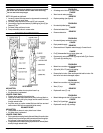
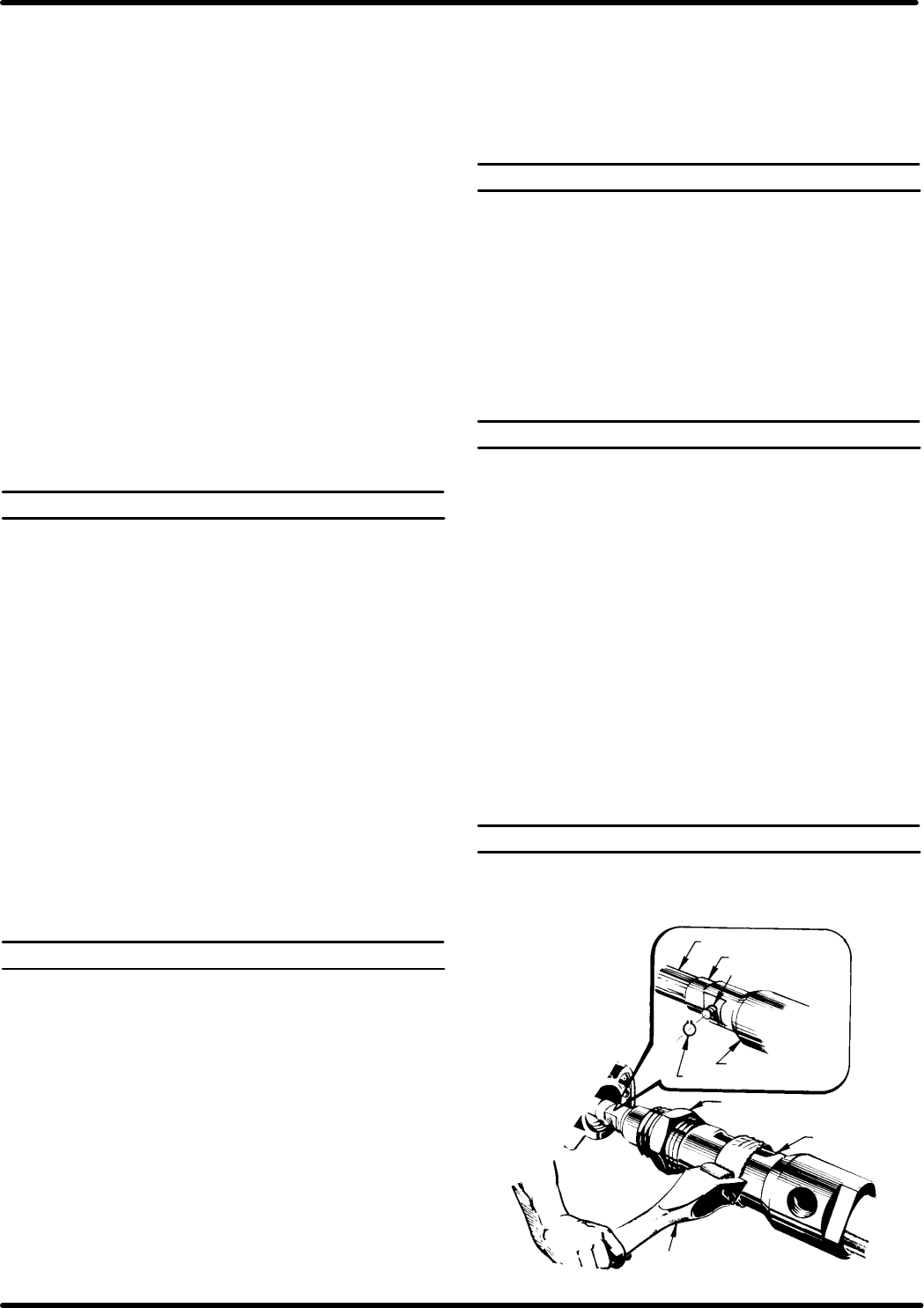
PUMP DISASSEMBLY
Special Tools:
• Strap wrench (PN 640081-B)
• Truarc retaining ring pliers (external)
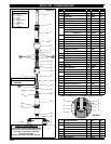
FIGURE 2
Air motor Piston Rod
Adapter
Pin
Pump Piston Rod
Snap Ring
Nut
Spacer Tube
640081-B
Strap Wrench
(Solvent Cup not shown)