


MDrive17Plus Microstepping REV060208 3
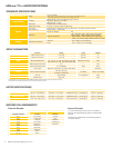
P1: I/O & POWER CONNECTOR
Pluggable
Terminal
Strip
Flying
Leads
Wire Colors
Pluggable
Locking Wire
Crimp**
Function
Universal Input
Differential Input
Clockwise/Counterclockwise
Pin 1 White Pin 3 Optocoupler Reference CW +
Pin 2
— — No Connect No Connect
Pin 3
Orange Pin 4 Step Clock Input CW –
Pin 4
Blue Pin 6 CW/CCW Direction Input CCW –
Pin 5 Brown Pin 5 Enable Input CCW +
Pin 6
Black Pin 1 Power Ground Power Ground
Pin 7
Red Pin 2 +V (+12 to +48 VDC) +V (+12 to +48 VDC)
Pin 7 +5 VDC Output
12-pin pluggable
locking wire crimp
connector not available
with Differential Input.
Pin 8 SPI Clock
Pin 9 Communications Ground
Pin 10 SPI Master Out – Slave In
Pin 11 SPI Chip Select
Pin 12 SPI Master In – Slave Out
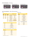
WIRE/PIN ASSIGNMENTS — MDrive17Plus Microstepping
P1: I/O, POWER & COMM CONNECTOR
M23 Circular
(Male)
Function
Pin 1 Optocoupler Reference
Pin 2 Enable Input
Pin 6 +V (+12 to +48 VDC)
Pin 8 SPI Master Out – Slave In
Pin 9 SPI Chip Select
Pin 10 +5 VDC Output
Pin 11 Communications Ground
Pin 12 Shell Connect
Pin 13 CW/CCW Direction Input
Pin 16 SPI Clock
Pin 17 SPI Master In – Slave Out
Pin 18 Step Clock Input
Pin 19 Power Ground
Pins below are No Connect unless populated for encoder option.
Optional Internal Differential Encoder
Pin 3 Index +
Pin 4 Channel B +
Pin 5 Channel B –
Pin 7 Channel A +
Pin 14 Index –
Pin 15 Channel A –
Plus-65 (sealed)Plus
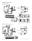
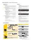
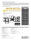
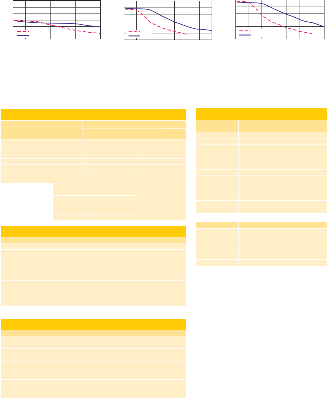
MOTOR PERFORMANCE — Speed-Torque
Single Length Rotary Motor Double Length Rotary Motor
Triple Length Rotary Motor
Torque in Oz-In
T
orque
i
n
N
-cm
S
p
eed in Full Ste
p
s
p
er Second
(
RPM
)
0
1000
2000
3000 4000
5000 6000 7000
(300)
(600)
(900) (1200)
(1500) (1800) (2100)
50
60
40
30
20
10
0
35
42
28
21
14
7
24 VDC
48 VDC
Torque in Oz-In
Torque in N-cm
Speed in Full Steps per Second (RPM)
0
1000
2000
3000 4000
5000 6000 7000
(300)
(600)
(900) (1200)
(1500) (1800) (2100)
50
60
40
30
20
10
0
24 VDC
48 VDC
42
35
28
21
14
7
Torque in Oz-In
T
orque
i
n
N
-cm
S
p
eed in Full Ste
p
s
p
er Second
(
RPM
)
0
1000
2000
3000 4000
5000 6000 7000
(300)
(600)
(900) (1200)
(1500) (1800) (2100)
50
60
40
30
20
10
0
35
42
28
21
14
7
24 VDC
48 VDC
P2: COMM CONNECTOR (SPI)**
10-Pin IDC Function
Pin 1 No Connect
Pin 2 No Connect
Pin 3 No Connect
Pin 4 SPI Chip Select
Pin 5 Communications Ground
Pin 6 +5 VDC Output
Pin 7 SPI Master Out – Slave In
Pin 8 SPI Clock
Pin 9 No Connect
Pin 10 SPI Master In – Slave Out
**The 12-Pin Pluggable Locking Wire Crimp connector at P1 eliminates the P2 connector.
P4: OPTIONAL INTERNAL DIFFERENTIAL ENCODER
10-Pin Wire Crimp Function
Pin 1 Ground
Pin 2 Channel A +
Pin 3 Channel A –
Pin 4 Channel B +
Pin 5 Channel B –
Pin 6 Index +
Pin 7 Index –
Pin 8 No Connect
Pin 9 No Connect
Pin 10 No Connect
An optional encoder cable is available.