


2 MDrive17Plus Microstepping REV060208
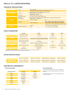
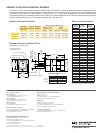
Holding Torque Detent Torque Rotor Inertia Weight (Motor+Driver)
SINGLE LENGTH
32 oz-in / 22.6 N-cm 1.66 oz-in / 1.17 N-cm 0.00053
oz-in-sec
2
/ 0.038
kg-cm
2
10.4 oz / 294.8 g
DOUBLE LENGTH
60 oz-in / 42.4 N-cm 2.08 oz-in / 1.47 N-cm 0.00080
oz-in-sec
2
/ 0.057
kg-cm
2
12.0 oz / 340.2 g
TRIPLE LENGTH
74.9 oz-in / 52.9 N-cm 3.47 oz-in / 2.45 N-cm 0.00116
oz-in-sec
2
/ 0.082
kg-cm
2
15.2 oz / 430.9 g
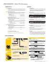
MDrive
17Plus
MICROSTEPPING
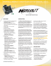
INPUT VOLTAGE (+V)
Range
+12 to +48 VDC
Power supply current requirements = 2A (maximum) per MDrive17Plus.
Actual power supply current will depend on voltage and load.
ISOLATED INPUT
Universal
Voltage Range: +5 to +24 VDC Sourcing or Sinking
Step Clock, Direction and Enable
Differential
Voltage Range: +5 VDC
Clockwise and Counterclockwise
MOTION
Digital Filter Range 50 nS to 12.9 µS (10 MHz to 38.8 kHz)
Clock Types Step/Direction, Quadrature, Step Up/Step Down, Clockwise/Counterclockwise
Step Frequency 2 MHz Default / 5 MHz Max
Resolution
Number of Settings 20
Steps Per Revolution
200,
400, 800, 1000, 1600, 2000, 3200, 5000,
6400, 10000, 12800, 20000, 25000, 25600,
40000, 50000, 51200, 36000 (0.01 deg/µstep),
21600 (1 arc minute/µstep), 25400 (0.001mm/µstep)
THERMAL
Operating Temperature
Heat Sink –40° to +85°C (non-condensing)
Motor –40° to +100°C (non-condensing)
STANDARD SPEC I FI CA TIONS
SETUP PARAMETERS
Function Range Units Default
MHC
Motor Hold Current 0 to 100 percent 5
MRC
Motor Run Current 1 to 100 percent 25
MSEL
Microstep Resolution
1, 2, 4, 5, 8, 10, 16, 25, 32, 50, 64, 100,
108, 125, 127, 128, 180, 200, 250, 256
µsteps per full step 256
DIR
Motor Direction Override 0/1 — CW
HCDT
Hold Current Delay Time 0 or 2–65535 mSec 500
CLK TYPE
Clock Type Step/Dir, Quadrature, Up/Down, CW/CCW — Step/Dir
CLK IOF
Clock and Direction Filter
50 nS to 12.9 µS
(10 MHz to 38.8 kHz)
nS ( MHz) 200 nS (2.5 MHz)
USER ID
User ID Customizable 1–3 characters IMS
EN ACT
Enable Active High/Low — High
Optional encoder cables are available.
MOTOR SPEC I FI CA TIONS
All parameters are set using the supplied IMS SPI Motor Interface GUI and may be changed on-the-fl y.
An optional Communication Converter is recommended with fi rst orders.
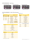
ENCODER PIN ASSIGNMENTS
DIFFERENTIAL ENCODER
with locking connector feature
SINGLE-END ENCODER
Pluggable Interface Function Function
Pin 1
No Connect Ground
Pin 2 +5 VDC Input Index
Pin 3 Ground Channel A
Pin 4 No Connect +5 VDC Input
Pin 5 Channel A – Channel B
Pin 6 Channel A +
Pin 7 Channel B –
Pin 8 Channel B +
Pin 9 Index –
Pin 10 Index +
Internal EncoderExternal Encoder
An internal differential encoder option is available on
MDrive17Plus Microstepping regular and IP65 sealed
versions.
See Wire/Pin Assignments on the following page for
connection details.