


GENERAL
5
Concord CXSi/H - Installation & Servicing
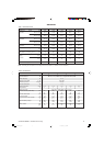
Boiler Size Cold Feed Open Vent
CXSi 110/H 1" 1
1/4"
CXSi 120/H 1" 1
1/4"
CXSi 140/H 1" 1
1/4"
CXSi 160/H 1
1/4"1 1/2"
CXSi 180/H 1
1/4"1 1/2"
1
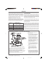
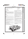
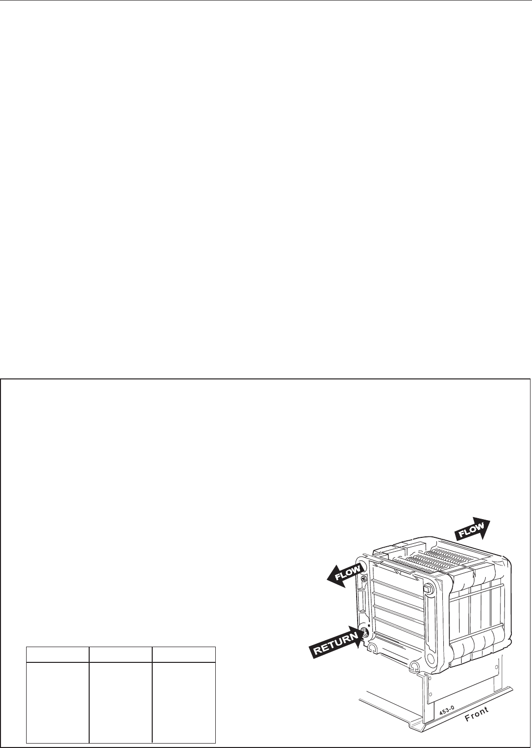
WATER CONNECTIONS
Flow connection is 65mm (2 1/2") nominal bore flange to
BS.4504 (PN6)
Return tappings are 2" BSP.
The distributor tube must be fitted into the return connection.
The flow header must be fitted in the flow pipe.
The open vent must be brought to either the 1
1/2" BSP tapping
on the flow header or to the unused 2" BSP tapping at the top
rear of the boiler.
The cold feed may be brought to the LH front bottom tapping in
order to avoid excessive surging or pumping over. The unused
bottom rear tapping must not be used for the cold feed pipe as
it is practically blocked by the distributor tube.
Safety Valve
A safety valve must be sized and fitted in accordance with BS.
6644 for every type of system. The valve should be set at 0.7
bar (10 lb/in.
2
) above the operating pressure in the boiler. The
maximum safety valve setting is 0.7 bar (10 lb/in.
2
) above the
maximum design operating pressure of 6.0 bar (87 lb/in.
2
).
FROST PROTECTION
Frost protection is incorporated in the boiler as long as there is a
permanent Live supply wired to Terminal L1 on the terminal plug-in
connection at the control box and the boiler thermostat knob is not
switched to Off.
If the temperature sensed by the boiler thermostat falls to about
5
0
C the boiler will fire until the temperature reaches 18
0
C.
Note that this is designed to protect the boiler and may not
necessarily protect remote parts of the system.
The mains voltage supply is via a terminal plug-in connection at the
control box.
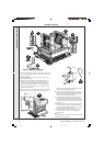
OPTION KITS
Remote Indication Kit
This kit gives the facility of remote indication of boiler status.
Pressure Gauge Kit
A pressure gauge kit is available.
DUTY
The range of boilers is suitable for: Combined indirect pumped
domestic hot water and central heating systems; Independent
indirect pumped domestic hot water or central heating systems.
Fully pumped systems may be open vented or sealed.
The range of boilers is NOT suitable for:
1. Gravity DHW systems.
2. Gravity heating systems.
3. Direct domestic hot water supply.
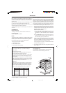
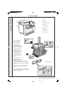
WATER CIRCULATION SYSTEM
Due to the compact nature of the boiler the heat stored within the
castings at the point of shutdown of the burner must be dissipated
into the water circuit in order to avoid the overheat thermostat
tripping. In order to allow pump operation after burner shutdown
the boiler control box incorporates a pump overrun facility which
operates for approximately 6 minutes after the burner shuts down
and, in order to make use of this, the pump must be wired to the
appropriate terminal L2 (pump) in the boiler control box.
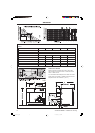
1. The minimum flow rate as given in Table 4 must be maintained
whenever the boiler is firing and during the pump overrun period.
2. During the period of pump overrun there must be an open circuit
of adequate water volume and/or load. The minimum size of
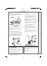
this circuit is given by the use of Graph 1.
Examples shown on Graph 1
a. For the CXSi 110/H and CXSi 120/H the minimum circuit
during pump overrun could be a load of 7 kW with a volume
of 42 litres or any other combination given by the relevant
line.
b. For the CXSi 180/H the minimum circuit during pump overrun
could be a load of 9 kW with a volume of 70 litres or any
other combination given by the relevant line.
The above circuit capacity during pump overrun may be achieved
either by provision of an adequate bypass circuit or by ensuring
that a zone of suitable size is open for circulation during this
period by relevant control of zone valves or pumps.
The wiring diagrams in Frames 16,17 &18 illustrate the control
methods for achieving the above.
3. Pump selection should take account of the hydraulic resistance
given in Graph 2.
Cold Feed/Open Vent
The independent cold feed and the open vent must comply
with BS. 6644 and be of the following minimum size.
157294-3.pmd 11/8/2005, 9:58 AM5