INSTALLATION
15
Concord CXSi/H - Installation & Servicing
12
CONTROL BOX
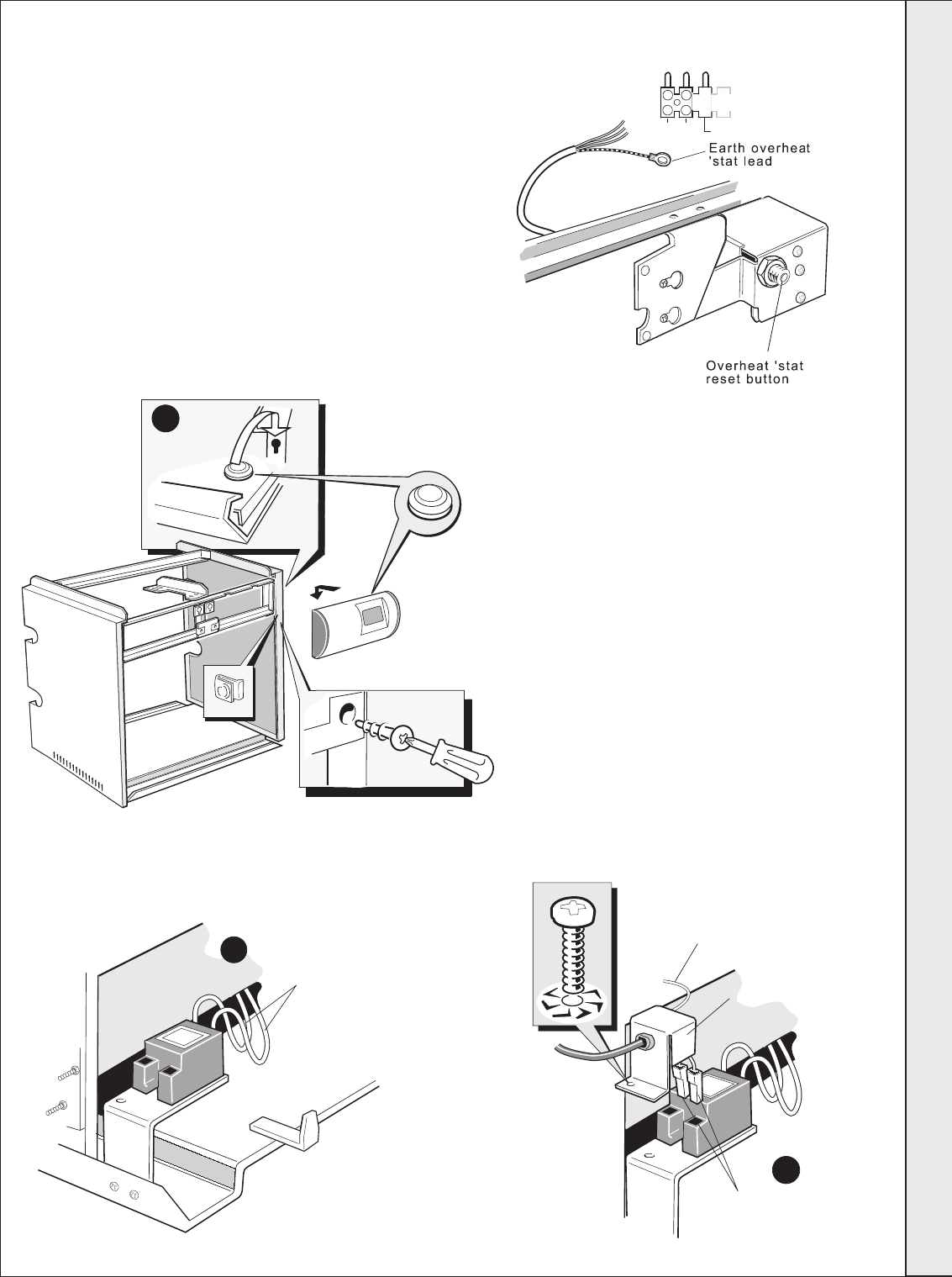
1. Make the 3 electrical connections from the overheat
thermostat (fixed to the upper front framework) to the
terminals marked 'Limit Stat' on the electrical plug-in
connector from the gas valve plug lead assembly, as
follows:
C Pink N/O Red N/C White
Ensure that the lead is securely fastened under the
strain relief clamp - but bring the earth wire outside
the clamp before tightening
2. Unpack the control box. Fit the plug-in connector
from the gas valve plug lead assembly to the bottom
box at the back of the control box and fasten, using
the M4 screws and washer.
Con 1309
C
N/O
N/C
2 push-in
connections
Con 1913
Electrical cover
Flame detector lead
6
3
Con 1468
5
Spark
generator
leads
Con 1912
3. Fit the control box to the support frame and fix
to the bottom, using the 2 self-tapping screws
provided.
4. Fit the earth connections from the terminal
plug-in connections to the appropriate earth
posts on the back of the control box. Connect
the earth lead prefitted to the control box back
panel to the threaded hole in the casing support
frame.
IMPORTANT
5. Offer up the spark generator assembly to the
combustion chamber base tray and secure the
bracket, using the M5 screws and washers.
Plug the spark generator leads onto the spark
electrode connections on the RH end burner -
access via the side of the combustion chamber.
6. Ensure the electrical cover is correctly fastened
to the spark generator.
INSTALLATION
157294-3.pmd 11/8/2005, 9:59 AM15


