6 42733-01 04/26/2007
ENGLISH
ASSEMBLY CONTINUED
6. Use pliers or an adjustable
wrench to tighten the Pole Set-
Screw until it seats rmly against
the Telescoping Pole. See Figures
1 and 2.
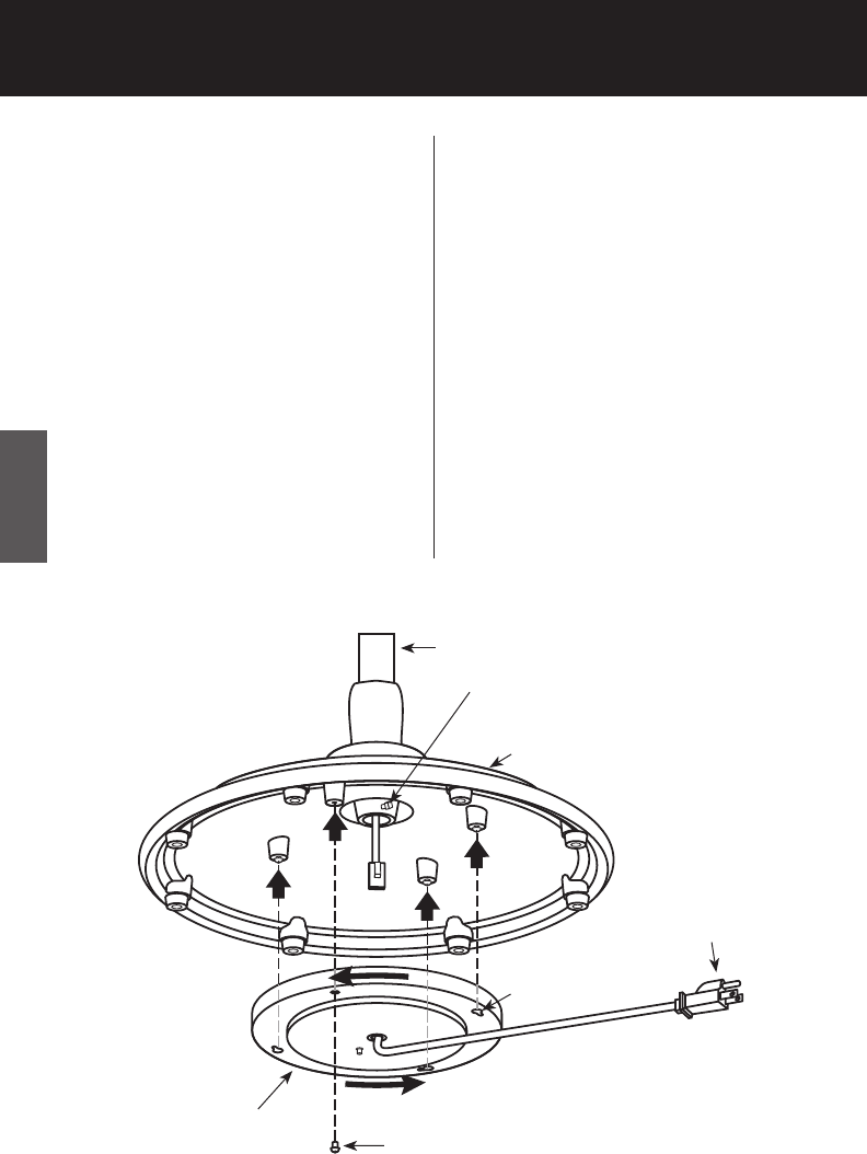
7. Connect the plugs coming from
the bottom of the Telescoping
Pole and the insdie of the Electri-
cal Cover.
Electrical
Cover
Cover Assembly Screw
Telescoping Pole
Base
Wall
Plug
FIGURE 2
Keyslots
8. Place the Electrical Cover against
the bottom of the Cast Iron
Base and align the Keyslots in
the Electrical Cover with the
three loosened Cover Assembly
Screws. Rotate the Electrical Cov-
er counterclockwise. See Figure
2.
9. Install the fourth Cover Assem-
bly Screw. Tighten all four Cover
Assembly Screws to attach the
Electrical Cover to the bottom
of the Cast Iron Base.
Pole Setscrew (NOTE: Pole Set-
screw must be tightened before
electrical cover is installed.)


