


10
11
ON
O
N
1
2
HE
HG
F
C
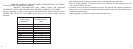
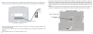
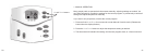
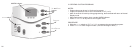
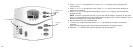
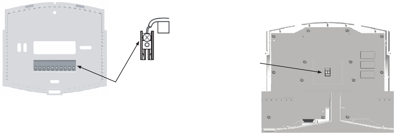
Connect Wires and Mount Thermostat to Wallplate
• Match and connect the labeled wires to the appropriate coded terminal screws on the wallplate. See
Figure 4. Ignore any wires which may be present, but which were not connected to the old thermostat.
R
Figure 4
Terminal Screws
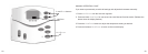
• Be sure to tighten the terminal screws securely, as a loose wire could cause operational problems with
your system or thermostat.
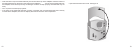
• Push excess wire back into the hole to prevent interference when installing the thermostat to the
wallplate.
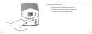
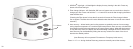
• SettheSystemSwitchto“off”,andtheFanSwitchto“auto”.
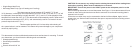
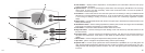
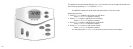
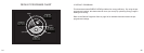
• OnthebackofthethermostataretheSystemSet-UpSwitches.SeeFigure5.(NOTE:Forclarity,the
illustration of the thermostat circuit board omits most of the circuit board components to clearly show the
System Set-Up Switches.) If the heat pump system has an electric auxiliary system, then slide the #1
switch to HE position. If the heat pump system has a gas auxiliary system, then slide #1 switch to the HG
position.
To set up the LCD display to show the temperature in Fahrenheit, slide the #2 switch to the F position. To
set up the LCD display to show the temperature in Celsius, then slide the #2 switch to the C position.
Figure 5
System Set-Up
Switches
Back of Thermostat