


If you have a hose without switches, the
Power Canister will start as soon as the
hose is inserted into the wall valve.
If you have a hose with a switch, then
the Power Canister can be turned ON or
OFF with the switch.
The Power Canister can also be turned
ON and OFF with the switch found on
the upper section of the motor module.
Check the System
Check each connection for proper seal
and that no air leaks occur. If one is pre-
sent, you may hear a “hissing” sound.
4
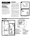
2. Installation
3. How to use
Location for power
canister
The Power Canister can be mounted in
the basement, utility room, garage or
any other remote area, except where
exposed to weather, and convenient to
an electrical outlet. The unit requires
ventilation. DO NOT install in a heat
producing or confined area such as the
attic, furnace room, etc. If desired, the
Power Canister can be exhausted to the
outside.
The top of the Canister should be no
less than 12” (30.5 cm) from the ceiling,
and any corner wall, to allow proper
cooling to the motor. For ease of remov-
ing the dust container, the bottom of the
unit should be at least 18” (46 cm)
above the floor.
Central Vacuum Power Canisters require
a separate/dedicated, 120 Volt, 60Hz.,
20 Amp, 3 wire grounded power circuit,
protected by a 120 Volt, 60 Hz., AC, 20
Amp time delay fuse or circuit breaker
and a 120 Volt, 60 Hz., 20 Amp ground-
ed receptacle.
If a 120 volt, 60 Hz., 20 Amp grounded
receptacle is not available, have a quali-
fied electrician install one for you. The
receptacle should be no more than 5
feet (152 cm) from the Power Canister.
UNDER NO CIRCUMSTANCES
SHOULD AN EXTENSION CORD BE
USED WITH THIS CANISTER.
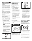
Mounting the power
canister
1) Determine if the wall you will be
mounting the Canister to is block,
concrete, or plaster/drywall.
2) Block or Concrete Wall
You will need (2) 1-1/2” (3.8 cm) x
1/4” (.64 cm) lead plugs and (2) 1-
1/2” (3.8 cm) x 1/4” (.64 cm) lag
bolts. Drill a 1/2” (1.3 cm) dia. x 1-
3/4” (4.4 cm) deep hole with a
masonry drill bit. Insert a lead plug
into the hole.
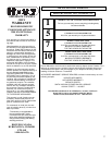
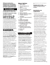
Mount the bracket (Fig. 2-1) from a
top hole with a lag bolt. Mark the
other upper hole of the bracket.
Make sure that the bracket is
straight. Slide the bracket away
from the mark and drill a hole direct-
ly over the mark.
Insert a lead plug into the hole.
Align the bracket over the hole and
tightly fasten with a lag bolt.
Continue to 4).
3) Drywall or Plaster Wall
You will need(2) 1-1/2” (3.8 cm) x
1/4” (.64 cm) wood screws. Locate
a stud and drill a 1/8” (.32 cm) dia.
x 1-3/4” (4.4 cm) pilot hole. Mount
the bracket from a top hole with a
wood screw. Make sure that the
bracket is straight. Drill a second
pilot hole using a lower hole on the
bracket and fasten tightly with the
other wood screw.
4) Mount the Power Canister on the
bracket making sure the bar on the
back of the machine is settled to the
bottom of the slots on the mounting
bracket. The wall mounting bracket
must fit between the two brackets
on the back of the central vacuum.
10) Plug the power cord in.
11) Assuming that the wall inlet valves
are connected, the system is now
ready.
3-1
3-2
A
A
A
B
2-1
2-2
5) Route the intake tubing to the
Canister.
6) Insert the tubing into the Canister
inlet.
7) Tighten the inlet connection with the
3” (7.6 cm) gear clamp (included).
(Do not cement pipe to plastic
inlet port.)
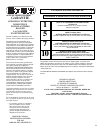
8) When venting the exhaust air, a
noise reducing exhaust muffler (A) is
included, which is installed inline in
the piping to vent outside or it can
be installed to vent indoors as
shown in Fig. 2-2. Connect to the
exhaust (right hand side near to of
unit). Tighten the exhaust connec-
tion with the gear clamp (included).
(Do not cement pipe to plastic
exhaust port.)
9) Connect the 24 Volt wires coming
from the wall valves into the 24 Volt
receptacle on the machine.
TOP
MOUNTING
BRACKET
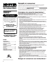
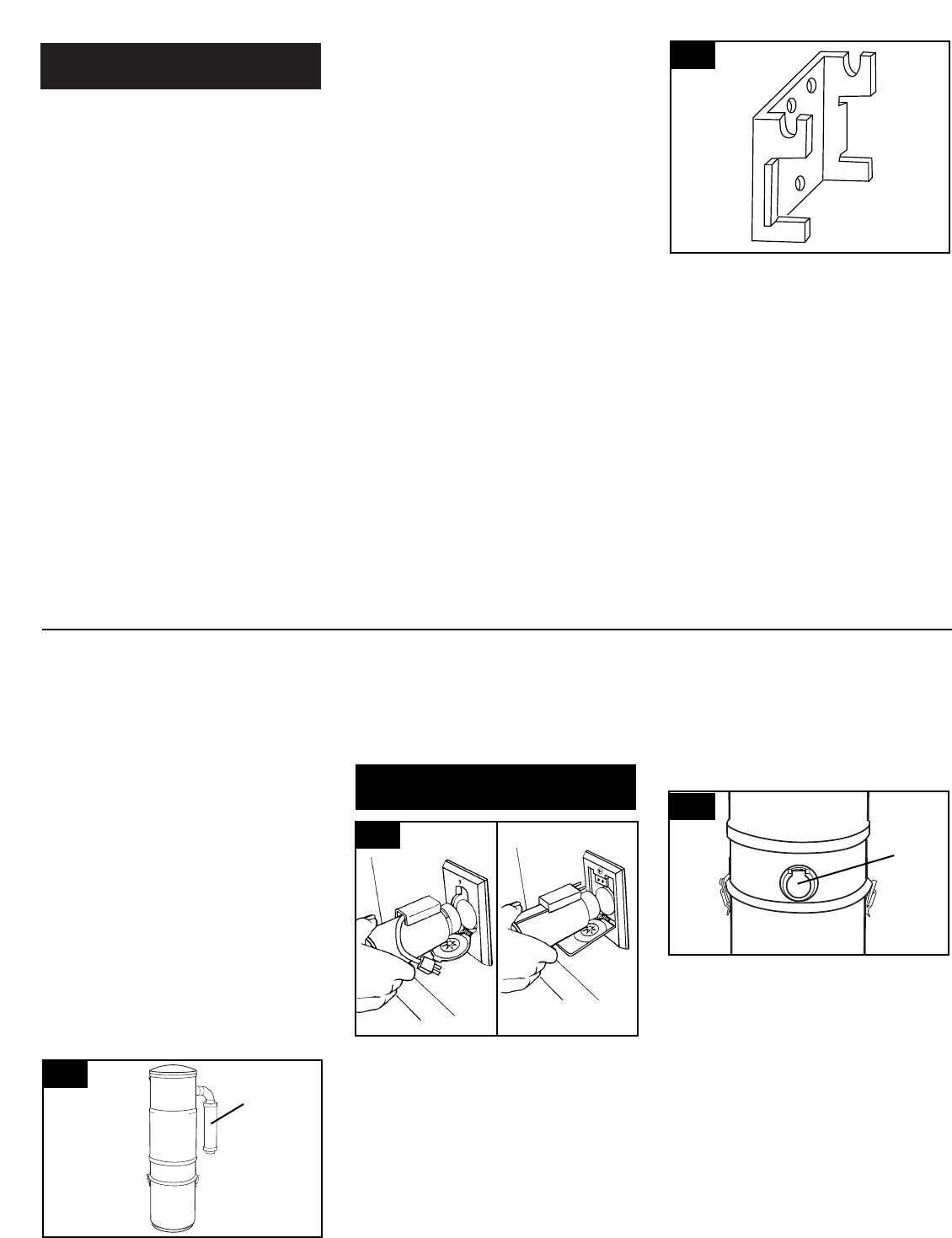
Hose inlet port (S5626 &
S5636 models only)
Insert the hose into the hose inlet (A) as
shown in Fig. 3-2. The power unit is
turned ON and OFF with the switch
found on the upper section of the motor
module.
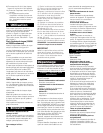
To start your Power Canister, simply plug
your hose end into any wall inlet valve.
Both types of wall valves (Standard (A) -
Corded Hose; Electrified (B) - Cordless
Hose) are shown in Fig 3-1.