


5 69-0637—2
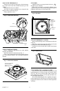
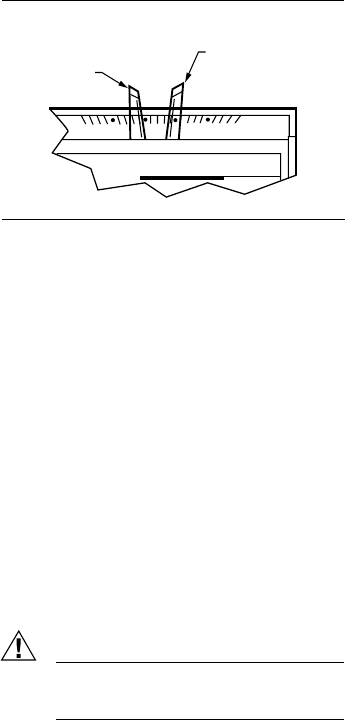
Fig. 10—Temperature control levers.
HEATING/COOLING SYSTEM
Turn on power to the furnace and cooling system.
Place the system switch lever to HEAT and fan switch
lever to AUTO.
Push both temperature setting levers together at least
5°F (3°C) above room temperature. The main burner should
come on. The fan will start when the furnace heats up. (If
central electric heat or heat pump system, fan starts imme-
diately.)
Move both levers 5°F (3°C) below room temperature.
The burner should shut off.
Place the system switch lever at COOL and the fan
switch lever at AUTO. The cooling equipment should
operate, and the fan will start. Allow for any time delay that
may be built into the compressor control circuit.
NOTE: To avoid compressor damage, do not operate the
system if outdoor temperature is below 50°F (10°C).
Refer to manufacturer recommendations.
Move both temperature setting levers together at least
5°F (3°C) above room temperature. The cooling equipment
should shut off.
Place the fan switch to ON. The fan should run continu-
ously with the system switch in any position.
Place the system switch to OFF. Move both temperature
setting levers to various positions. The heating and cooling
systems should not operate.
Operate the entire system for at least one complete cycle
with the system switch at COOL and one complete cycle
with the switch at HEAT.
If thermostat fails any test, refer to the Troubleshooting
Guide in the Owner’s Manual.
Reset both temperature setting levers to the desired
temperatures.
Leave Owner’s Manual and Assistance Information in a
convenient place for the building occupant or provide with
other appliance manuals.
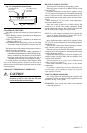
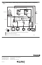
TYPICAL WIRING DIAGRAMS
For wiring, follow the hookup diagram supplied with
your heating, cooling or heating/cooling equipment. If not
available, use Fig. 11 as a guide.
REMEMBER: Your wiring must follow local electrical
codes and ordinances.
50
60
70
80
HIGH TEMPERATURE
(RED MARK)
SET LEVER
LOW TEMPERATURE
(BLUE MARK)
SET LEVER
M859
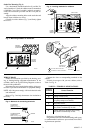
SET SUBBASE SWITCHES
The subbase system switch controls system operation as
follows:
HEAT: Heating system is controlled by the thermostat.
Cooling system is off.
COOL: Cooling system is controlled by the thermostat.
Heating system is off.
OFF: Both the heating and cooling systems are off. If the
fan switch is in the AUTO position, the fan is also off.
The subbase fan switch controls fan operation as follows:
ON: Fan operates continuously.
AUTO: Fan operates with the cooling equipment as
controlled by the thermostat or with the heating equip-
ment as controlled by the plenum switch. In electric
heat, heat pump and fan coil systems, the fan is
controlled by the thermostat in heating and cooling.
To switch positions, use thumb or index finger to slide
lever to the desired position. Switch lever must stop in
detent over the desired function indicator mark for proper
circuit operation.
CHECK OUT THERMOSTAT OPERATION
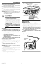
CAUTION
Do NOT check operation by shorting across
terminals of relay or valve coil; this will burn
out the thermostat heat anticipator.