


3 69-0637—2
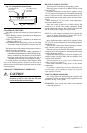
Outlet Box Mounting (Fig. 4)
Use a horizontally mounted outlet box if possible. If a
vertical outlet box is used, the subbase must be mounted on
a 202689A Cover Plate Assembly (ordered separately).
Follow the instructions provided with the cover plate as-
sembly.
Align the subbase mounting holes on the outlet box and
loosely fasten with the two screws.
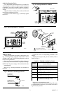
Carefully level the subbase (Fig. 3) and firmly tighten
the screws.
Fig. 3—Leveling methods for subbase.
AUTO OFF
COOL
HEATON
FAN
B
O
W
Y
R
G
M1555
SPIRIT LEVEL
PLUMB
LINE
PLUMB
BOB OR
WEIGHT
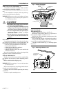
Fig. 4—Mounting subbase on outlet box.
M1554A
B
O
W
Y
R
G
VERTICAL
OUTLET
BOX
ADAPTER
RING
1
2
NOT INCLUDED WITH UNIT.
ACCESSORY PARTS AVAILABLE.
SUBBASE OR
WALLPLATE
1
2
2
COVER
PLATE
MOUNTING
SCREWS (2)
M1553A
EXISTING
HORIZONTAL
OUTLET BOX
HEATING/
COOLING
SUBBASE
AUTO OFF
COOL
HEATON
FAN
R
G
O
W
Y
B
WIRE SUBBASE
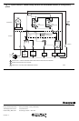
Follow the instructions provided by the heating, cool-
ing, or heating/cooling equipment manufacturer. If not
available, refer to the Typical Wiring Diagrams section at
the end of this publication.
Disconnect the power supply before making wiring con-
nections to prevent electrical shock or equipment damage.
NOTE: All wiring must comply with local electrical codes
and ordinances.
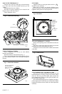
Refer to Fig. 5 and strip thermostat wire insulation as
necessary.
Fig. 5—Methods of connecting terminals.
Connect the wires to corresponding terminals on the
subbase.
If labels do not agree with your new subbase, refer to
Table 2 or Fig. 11.
TABLE 2—TERMINAL DESIGNATIONS.
Subbase
Terminal Control Function
R Control transformer power.
W Heating control circuit.
Y Cooling control circuit (jumper to W for
heat pump compressor control).
G Fan control circuit.
O Cooling damper or changeover/reversing
valve, makes continuously in cool.
B Heating damper or changeover/reversing
valve, makes continuously in heat.
BARRIER
FOR WRAPAROUND
CONNECTION—
STRIP 7/16 in. [11 mm]
FOR STRAIGHT
CONNECTION—
STRIP 5/16 in. [8 mm]
M1556B
Push excess wire back into the wall.
Plug the hole in the wall with nonhardening caulk, putty,
or nonflammable insulation to prevent drafts from affect-
ing thermostat operation.