


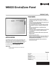

W8835 ENVIRAZONE PANEL
5 68-0258—04
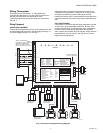
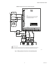
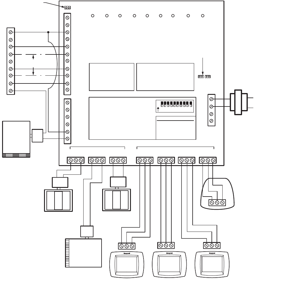
Wiring Thermostats
Run wire from the Thermostat 1, 2, 3 terminals to the
corresponding terminals on any one of the EnviraCom bus
terminal sets. More than one thermostat or other
communicating device can be connected to a bus terminal.
See Fig. 3.
Wiring Equipment
CONVENTIONAL EQUIPMENT
Connect the first stage heat to W1/E, second stage heat to W2,
and third stage heat to W3/Aux. Wire first stage cooling to Y1,
and second stage cooling to Y2. See Fig. 3.
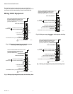
If separate HVAC equipment transformers are used for the
heating and cooling systems, such as for an oil furnace, wire
the heating transformer hot wire to Rh and the cooling
transformer hot wire to Rc. Locate the Rh/Rc jumper above the
equipment terminals and remove the jumper to expose the two
pins.
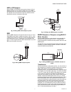
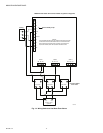
HEAT PUMP EQUIPMENT
Connect the Y1 terminal to the first stage compressor, and the
Y2 terminal to the second stage compressor. W3/Aux is the
auxiliary heat and W1/E is the emergency heat. If emergency
heat and auxiliary heat use the same piece of equipment,
place a jumper from W3/Aux to W1/E and wire it to the resistive
heat equipment. See Fig. 4 and 5. See Fig. 6 and 7 for two-
stage heat pump equipment.
Fig. 3. Conventional equipment wiring diagram.
12 3
12 3
12 3
L
C
RH
RC
W1 /E
W2
W3/AU X
Y1
Y2
G
O/ B
HU M
HU M
DE HUM
DE HUM
VE NT
VE NT
R
C
T1
T2
ZONE 1
M6 M4 M1
ZONE 2
M6 M4 M1
ZONE 3
M6 M4 M1
1 2 3 1 2 3 1 2 3 1 2 3
DA MP ER S E NV IR A C OM BUS
DAM PER
XF R M
EN VI RACO M
XF R M
RE MO VE JU M PER S IF
T1 AND T2 ARE USED
HE AT CO OL ZO NE 1 CO M EM HE AT FA N PU R G EZ ON E 3 ZO NE 2
W8835A
DI P SW IT C H SE TT IN GS
1 SEE TA BL EO NO FF
2 SEE TA BL E1 0
3 EN VI RACO M FU RN NO YE S
4 P URG E TI ME 2 MI N3 .5 MI N
5 P URG E FA NH VA C P ANE L
6 P URG E DAM PE RN O CHG OP EN
7 # CO MP ST AG ES 1 2
8 HE AT FA NH VA C P ANE L
9 HP CHANG EO VE RO B
10 UNU SE D
O
N
1 2 3 4 5 6 7 8 9 10
#1 #2 CO NV HT ST G
1 1 1
1 0 2
0 1 3
0 0 HP
24 VOLT/40 VA
TR AN SF O R ME R
R
C
L1
L2
R
W1
W2
Y1
Y2
G
C
DO TTE D LI NE S FO R 2-
ST AG E A PPL IC AT IO NS
SI NG LE TR AN SF OR ME R
H EAT IN G/COOLING SYST EM S
RE QU IR E A JU M PER TO BE
IN ST AL L E D CO NNEC TI NG RH
AND RC (FACTORY INSTALLED) .
12 3
EARD- 6
M31122
POWER-CLOSED/
SPRING-OPEN
ZD DAMPER
POWER-CLOSED/
SPRING-OPEN
ZD DAMPER
POWER-CLOSED/
SPRING-OPEN
ARD DAMPER
C7835A DISCHARGE
AIR SENSOR
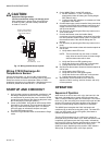
LED STATES:
Heat LED Heating Mode
Cool LED Cooling Mode
Purge LED Purge Mode
Fan LED Fan Mode
Em Heat LED Em Heat Mode
COMM LED Communications
ZONE LEDS:
On Damper open or opening
Off Damper closed or closing
MOMENTARY PUSH BUTTONS
Boot Clears Microprocessor
Purge Override Bypass Purge Mode
Discovery Initiates Discovery Mode