


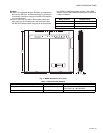
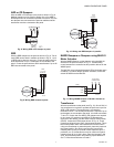
W8835 ENVIRAZONE PANEL
11 68-0258—04
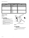
Discharge Air Temperature Sensor
DATS
The C7835A1009 Discharge Air Temperature Sensor (included
in the Y8835 kits) is a supply-duct-mounted temperature
sensor probe used to control capacity and prevent high plenum
temperatures or coil-icing. The sensor is wired to the
EnviraCom bus using three wires. When a high or low limit is
reached, the panel shuts off the equipment and keeps the fan
operating for a minimum of two and one-half minutes. After this
time, and any applicable minimum-off times imposed by the
HVAC equipment. It re-energizes the equipment when the
discharge air has recovered by ten degrees. When the high or
low limit is exceeded, the Heat (red) or Cool (green) LED on
the DATS flashes.
When the DATS is in a limit condition, the Heat, Cool and
Purge LEDs on the W8835 panel continue to operate as if the
DATS were not turning the equipment off.
The high and low limit is set on the DATS. The high
temperature limit is set from 110°F to 160°F with a small
screwdriver or using fingers and the low limit is set at 40°F or
48°F degrees with a jumper.
Circuit Breaker Protection
A built-in thermal circuit breaker protects the EnviraZone panel
against shorts in the damper wiring and EnviraCom bus. It
does not protect against shorts in the HVAC equipment wiring
into the panel.
When the circuit breaker is tripped, none of the LEDs illuminate
and the yellow rectangular component located bottom center
on the panel is hot to touch.
• Remove power to the panel for at least five minutes to allow
the circuit breaker to cool off and reset.
• To eliminate the short, verify the dampers and transformer
wiring.
Fan On In Heat
The system blower can be set to come on with a call for heat
as required for hydro-air or electric heat systems. Set the
blower function using DIP switch 8. When configured for heat
pump, this DIP switch is not used.
Table 10. Fan-in-heat Configuration
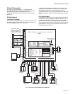
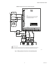
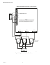
Adding Additional Zones
Connect one W8703 to the EnviraCom bus to expand the
system up to six zones or connect two W8703 to control up to
nine zones:
• Wire the first three zone dampers and thermostats to the
W8835 Envirazone Panel.
• Wire the additional dampers to the W8703 panels.
• Set the DIP switches on the W8703 to correspond to the
zones being controlled. See W8703 Installation Instructions.
• Wire terminals 1, 2, and 3 from the additional thermostats to
terminals 1, 2, and 3 on any of the panels.
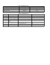
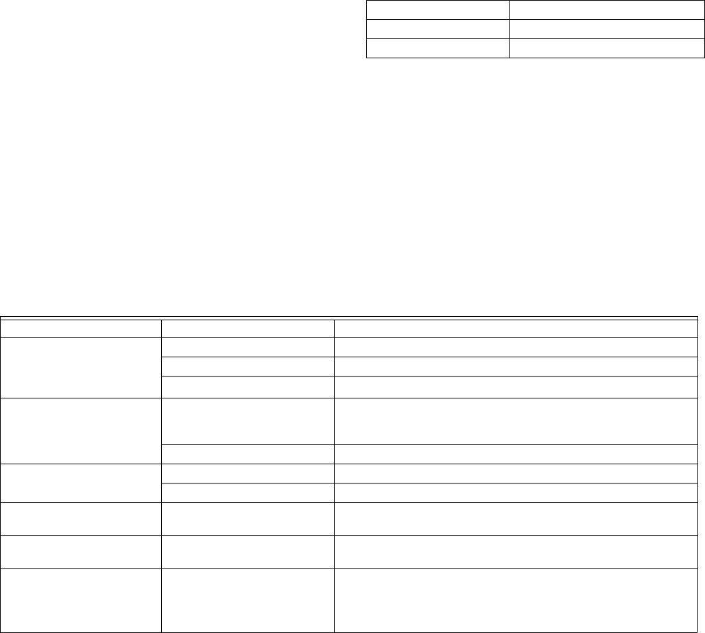
TROUBLESHOOTING
Table 11. Troubleshooting
DIP Switch 8 Fan Control
Off (Down) Fan on in heat by panel.
On (Up) HVAC control of fan.
Symptom Possible Cause Action
No LEDs are Illuminated. No power to the board. Check for 24 Vac (±10%) across R and C.
Transformers out of phase. If 48 Vac across R and T1, reverse T1 and T2 wires.
Shorted wire. Check thermal circuit breaker. If hot, a short exists in wiring.
Damper LEDs on, but no
other LEDs illuminate on a
call for heat, cool, or fan.
Insufficient voltage. Check for 24 Vac (±10%) across R and C.
Incorrect configuration. Check jumpers and DIP switches for correct configuration.
Heat pump operates
incorrectly or not at all.
Incorrect wiring. Verify equipment terminals wiring.
Incorrect configuration. Verify DIP switches configuration.
No damper LEDs are
illuminated.
Incorrect configuration. Verify that XFRM jumpers are set correctly.
Error 35 or 39 message on
thermostats.
Incorrect zone numbers. Verify the thermostat zone numbers are set correctly (1,2,3 etc)
Wait is continuously in the
thermostat display
Incorrect configuration Verify dip switch 3 is set to conventional (Up) position. If
controlling a heat pump, verify that thermostats are not configured
to lockout the compressor based on outdoor temperature.
(This feature is not used on zoned applications)