


69-0668—1
6
VR8300A CONTINUOUS PILOT COMBINATION GAS CONTROL
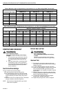
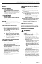
Table 5. Maximum Length of Supplementary Limit Leadwires in in. (m) When Using Q340A Thermocouple.
Maximum Leadwire Length x 2 (Wires)
Thermocouple Length AWG No. 14 AWG No. 16 AWG No. 18
in. m in. m in. m in. m
18 0.5 35 0.9 22 0.6 13 0.3
24 0.6 29 0.7 18 0.5 11 0.3
30 0.8 23 0.6 15 0.4 9 0.2
36 0.9 17 0.4 11 0.3 6 0.2
48 1.2 DO NOT USE.
60 1.5
Table 6. Maximum Length of Supplementary Limit Leadwires in in. (m) When Using Q390/Q340 Thermocouple.
Maximum Leadwire Length x 2 (Wires)
Thermocouple Length AWG No. 14 AWG No. 16 AWG No. 18
in. m in. m in. m in. m
12 0.3 47 1.2 30 0.8 18 0.5
18 0.5 41 1.0 26 0.7 16 0.4
24 0.6 35 0.9 22 0.6 14 0.4
30 0.8 29 0.8 18 0.5 11 0.3
36 0.9 23 0.6 15 0.4 9 0.2
40 1.0 19 0.5 12 0.3 7 0.2
48 1.2 11 0.3 7 0.2
60 1.5 DO NOT USE.
START-UP AND CHECKOUT
WARNING
Fire or Explosion Hazard.
Can cause property damage, severe injury,
or death.
1. Do not force the gas control knob. Use only
your hand to push down the reset button or
turn the gas control knob. Never use any
tools.
2. If the gas control knob or reset button does
not operate by hand, or if the reset button
stays depressed after it is released, the gas
control should be replaced by a qualified
service technician.
Gas Control Knob Settings
The gas control knob has three settings:
OFF: prevents pilot and main burner gas flow.
PILOT: permits pilot gas flow only. Gas control knob
must be held depressed or thermocouple must be
heated sufficiently to hold the safety control valve
open.
ON: permits main burner and pilot gas flow. Thermostat
and gas control the main burner gas flow.
NOTE: Gas controls are shipped with the gas control
knob in the ON position.
Perform Gas Leak Test
WARNING
Fire or Explosion Hazard.
Can cause property damage, severe injury,
or death
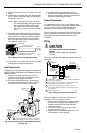
Check for gas leaks with rich soap and water
solution any time work is done on a gas control.
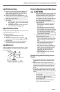
Gas Leak Test
1. Paint the pipe connections upstream of the gas
control with a rich soap and water solution. Bubbles
indicate a gas leak.
2. If a leak is detected, tighten the pipe connection.
3. Stand clear while lighting the main burner to prevent
injury caused from hidden gas leaks that could
cause flashback in the appliance vestibule. Light the
main burner.
4. With the main burner in operation, paint pipe joints
(including adapters) and gas control inlet and outlet
with rich soap and water solution.
5. If another leak is detected, tighten the adapter
screws, joints, and pipe connections.
6. Replace the part if gas leak cannot be stopped.