


69-0668—1
5
VR8300A CONTINUOUS PILOT COMBINATION GAS CONTROL
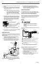
GAS CONTROL
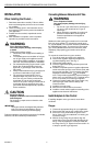
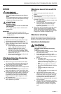
TIGHTEN NUT ONE TURN
BEYOND FINGER TIGHT.
FITTING BREAKS OFF AND CLINCHES
TUBING AS NUT IS TIGHTENED.
TO PILOT
BURNER
M3076A
2. Square off and remove the burrs from the end of the
tubing.
3. Unscrew the compression fitting from the pilot outlet
(Fig. 5). Slip the compression fitting over the tubing
and slide out of the way.
NOTE: When replacing a gas control, cut off the
old compression fitting and replace with the
new compression fitting provided on the
gas control. Never use the old compres-
sion fitting as it may not provide a gas-tight
seal.
4. Push tubing into the pilot gas tapping on the outlet
end of the control until it bottoms. While holding the
tubing all the way in, slide the compression fitting
into place and engage threads—turn until finger-
tight. Then tighten one more turn with wrench. Do
not overtighten. Refer to Fig. 7.
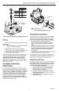
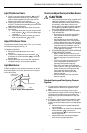
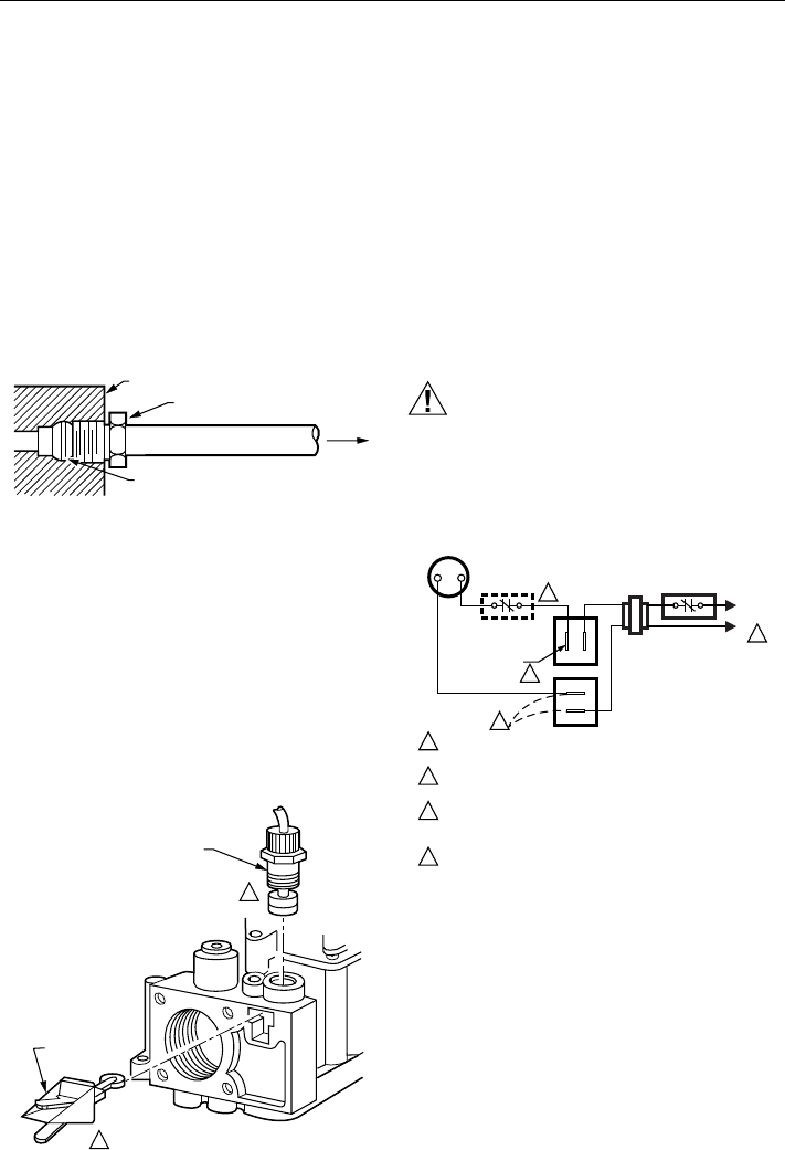
THERMOCOUPLE
LEAD
ECO
CONNECTOR
1
THIS IS AN ELECTRICAL CONECTION AND MUST BE
CLEAN AND DRY. DO NOT USE PIPE COMPOUND.
M3095
1
Fig. 8. Install thermocouple, optional ECO connector
to power unit.
3. For attachment nut type pilot burners: From
beneath, insert the tip of the Q340 into the hole or
barrel in the pilot burner. Engage the threads of the
attachment nut and tighten securely.
Connect Thermocouple
If a supplementary limit or energy cutoff (ECO) is used,
insert the ECO connector (order part no. 394332 as shown
in Fig. 8) and then connect the thermocouple lead.
Otherwise, insert the thermocouple lead directly.
This is an electrical connection and must be clean and dry.
Never use pipe compound. Tighten only 1/4 turn beyond
finger-tight to give good electrical continuity.
Do not
overtighten
.
Wiring
CAUTION
Hazardous Voltage.
Can cause personal injury or equipment
damage.
Disconnect power supply before installing or
servicing.
All wiring must comply with applicable electrical codes and
ordinances.
Fig. 7. Always use new compression fitting.
5. Connect other end of tubing to pilot burner according
to pilot burner manufacturer instructions.
Install Thermocouple
The Q340A Thermocouple (with adapters) is provided with
SUPER TRADELINE® models of the VR8300A. Install the
Q340A as follows:
1. Determine if the pilot burner requires a thermo-
couple with a push-in clip or attachment nut, and
attach the correct adapter to the Q340.
2. For push-in clip type pilot burners, from beneath,
insert the tip of the Q340 into the hole or barrel of
the pilot burner. Push in firmly to lock in place.
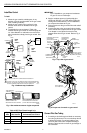
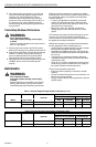
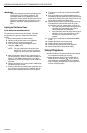
L1
(HOT)
L2
1
24V
THERMOSTAT
OPTIONAL
CONVENIENCE
TERMINALS
TH/TR
TH
TR
GAS CONTROL
TERMINALS
HIGH LIMIT
CONTROLLER
POWER SUPPLY. PROVIDE DISCONNECT MEANS AND OVERLOAD
PROTECTION AS REQUIRED.
DO NOT JUMPER THESE TERMINALS. THIS SHORTS VALVE COIL
AND CAN BURN OUT ANTICIPATOR IN THERMOSTAT.
CONVENIENCE TERMINALS SERVE ONLY AS A TIE POINT.
THEY ARE NOT INTERNALLY WIRED TO THE CONTROL CIRCUIT
OR TO GROUND.
OPTIONAL HIGH LIMIT.
1
2
3
4
2
3
4
M2915
Fig. 9. Wiring connections for 24V control.
Refer to the appliance manufacturer instructions if
available, or use the following procedure.
1. Check the power supply rating on the gas control
and make sure it matches the available supply.
Install the transformer, thermostat, and other
controls as required.
2. Connect the control circuit to the gas control
terminals. See Fig. 5 and 9.
3. Adjust the thermostat heat anticipator to the 0.70
rating stamped on valve operator.