


69-0668—1
3
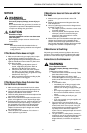
VR8300A CONTINUOUS PILOT COMBINATION GAS CONTROL
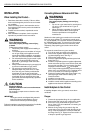
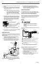
COLOR CODE FOR
LP
GAS
NATRUAL
GAS
CAP SCREW BLACK SILVER
PRESSURE
REGULATOR
ADJUSTING
SCREW
WHITE WHITE
TAPERED
SPRING
RED
STAINLESS
STEEL
PRESSURE
REGULATOR
HOUSING
M16015
Fig. 1. Install conversion kit in regulated gas control.
Bushings:
1. Remove the seal over the gas control inlet or outlet.
IMPORTANT
On LP installations, use a compound resistant to
LP gas. Do not use Teflon tape.
2. Apply moderate amount of good quality pipe
compound to bushing, leaving two end threads bare.
3. Insert bushing in gas control and thread pipe
carefully into bushing until tight.
Follow the instructions below for piping, installing control,
connecting pilot tubing, thermocouple and wiring. Make
certain the leak test you perform on the control after
completing the installation includes leak testing the
adapters and screws. If you use a wrench on the valve
after flanges are installed, use the wrench only on the
flange, not the control.
Use Adapters to Solve Swing
Radius Problems
In some field service applications, it is difficult or impos-
sible to thread the gas control onto the gas supply pipe
because of space limitations. This problem can usually be
resolved by using an adapter. The adapter is installed on
the end of the supply pipe in place of the gas control,
following the same precautions and instructions that are
used for installing the gas control. After the adapter is
installed, the gas control is attached to the adapter as
outlined above. Note that using an adapter increases the
overall length of the gas control.
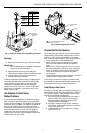
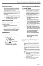
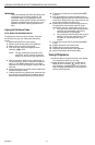
Fig. 2. Install flange to gas control.
Choose Gas Control Location
Do not locate the gas control where it can be affected by
steam cleaning, high humidity, dripping water, corrosive
chemicals, dust or grease accumulation, or excessive
heat. To ensure proper operation, follow these guidelines:
• Locate gas control in a well ventilated area.
• Mount gas control high enough above the cabinet
bottom to avoid exposure to flooding or splashing
water.
• Make sure the ambient temperature does not exceed
the ambient temperature ratings for each component.
• Cover gas control if appliance is cleaned with water,
steam, or chemicals or to avoid dust and grease
accumulation.
• Avoid locating gas control where exposure to corrosive
chemical fumes or dripping water is likely.
Locate the gas control in the appliance vestibule on the
gas manifold. In replacement applications, locate the gas
control in the same location as the old gas control.
Install Piping to Gas Control
All piping must comply with local codes and ordinances or
with the National Fuel Gas Code (ANSI Z223.1 NFPA No.
54), whichever applies. Tubing installation must comply
with approved standards and practices.
1. Use new, properly reamed pipe free from chips. If
tubing is used, make sure the ends are square,
deburred and clean. All tubing bends must be
smooth and without deformation.
2. Run pipe or tubing to the gas control. If tubing is
used, obtain a tube-to-pipe coupling to connect the
tubing to the gas control.
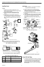
3. Install sediment trap in the supply line to the gas
control. See Fig. 3.
M803
FLANGE
GAS CONTROL
INLET
9/64 IN. (3.6 MM)
HEX SCREWS (4)
1 DO NOT OVERTIGHTEN SCREWS.
TIGHTEN TO 25 IN. LB.
1