TZ-3 TOTALZONE® ZONE CONTROL PANEL
5 68-0223-2
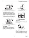
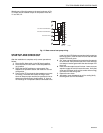
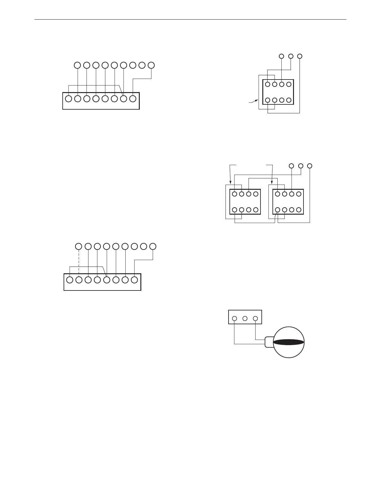
Fig. 4. Heat pump thermostat with separate Y1 and W1
terminals and multi-stage thermostat wiring.
If the thermostat selected has a sin
g
le Y terminal, see Fi
g
. 5.
Select a sin
g
le Y thermostat for each zone. See Table 1.
Set DIP switch 6 or 7
(
not both
)
to the On
p
osition. Set switch
6 to On when B on the thermostat is wired to W on the
p
anel.
Set switch 7 to On when 0 on the thermostat is wired to W on
the
p
anel.
When usin
g
the zone thermostat to control the second sta
g
e
of heat
(
W2
)
, set DIP switch 5 to On, and DIP switch 1 to Off.
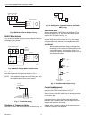
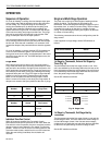
Fig. 5. Heat pump thermostat with single Y thermostat
wiring.
AOBD Dampers
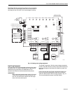
Wire the AOBD, AOBD-BM and IOBD Dam
p
ers to the
p
anel
as shown in Fi
g
. 6. See Fi
g
. 7 when usin
g
two dam
p
ers on
one zone. When three or more dam
p
ers are controlled on
one zone, a slave dam
p
er control rela
y
(
SDCR
)
is re
q
uired.
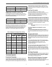
Fig. 6. AOBD single damper wiring.
Fig. 7. AOBD multiple damper wiring.
ARD or ZD Dampers
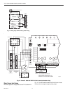
Wire the ARD or ZD Dam
p
er to the
p
anel as shown in Fi
g
. 8.
Multi
p
le dam
p
ers can be wired in
p
arallel. When ARD or ZD
dam
p
er is used, the zone LEDs switch directl
y
from red to
g
reen
(
never amber
)
.
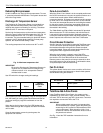
Fig. 8. ARD or ZD Damper wiring.
MARD or CDO-51 Dampers
Wire the MARD or CDO-51 Dam
p
er to the
p
anel as shown in
Fi
g
. 9. These are floatin
g
control modulatin
g
dam
p
ers, but are
controlled as two-
p
osition dam
p
ers on the TZ-3
p
anel.Two
dam
p
ers can be wired in
p
arallel.
LW2 G Y R W M6
GLW2E Y1 R W1 C/X
M4 M1
THERMOSTAT
ZONE CONNECTIONS ON PANEL
ZONE THERMOSTAT
M19065
MOTOR
LGYR W M6
E W2 L G Y R O C/X
M4 M1W2
THERMOSTAT
ZONE CONNECTIONS ON PANEL
HEAT PUMP ZONE THERMOSTAT
M19066
MOTOR
4
M6 M4 M1
5 6
123
Z
X
DAMPER MOTOR
FIELD JUMPER
M19067
MOTOR TERMINALS
4
M6 M4 M1
5 6
123
DAMPER MOTORS
M19068
MOTOR TERMINALS
4 5 6
123
Z
X
Z
X
FIELD JUMPER
M6 M4 M1
M19037A
DAMPER TERMINALS
ON PANEL
POWER CLOSE
SPRING OPEN
MODEL ARD, ZDS, ZDB


