TZ-3 TOTALZONE® ZONE CONTROL PANEL
11 68-0223-2
.
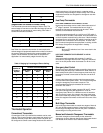
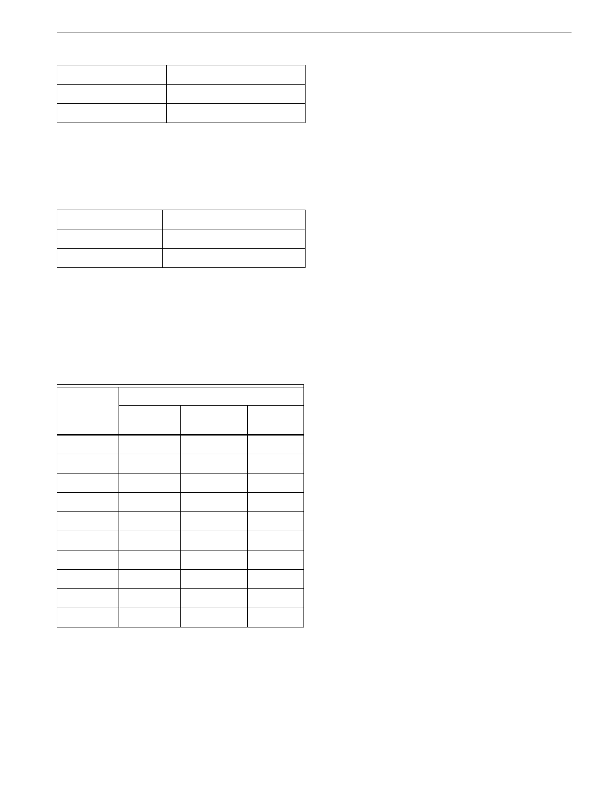
Stages Based On Number of Zones Calling
The thermostat controls the first sta
g
e of heat or cool. The
second sta
g
e of heat and cool and the third sta
g
e of heat are
ener
g
ized b
y
the
p
ercenta
g
e of zones callin
g
. See Table 4.
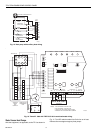
Set the DIP switches as follows:
See Table 4 to determine the number of zones re
q
uired to
activate sta
g
es of e
q
ui
p
ment based on the number of zones in
the s
y
stem. Sta
g
in
g
is based on the zones available in the
s
y
stem, not the number of zones used for the
p
articular
a
pp
lication. As zones satisf
y
, sta
g
es 2 and 3 dro
p
out.
Thermostat Operation
Conventional Thermostats
Conventional
(
R,W,Y,G
)
heat/cool thermostats can be used
with the TZ-3 to control sin
g
le or multi-sta
g
e
g
as, electric or oil
s
y
stems and heat
p
um
p
s with auxiliar
y
heat. The
p
anel can
be confi
g
ured to control second sta
g
e heat and cool and third
sta
g
e heat usin
g
a 5-30 minute
p
anel, or sta
g
in
g
can be
controlled b
y
the
p
ercenta
g
e of zones callin
g
. The O and B
e
q
ui
p
ment terminals are ener
g
ized for chan
g
eover use with
heat
p
um
p
s.
Heat Pump Thermostats
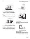
HEAT PUMP THERMOSTATS WITH SINGLE Y OUTPUT
Heat
p
um
p
thermostats can be used if thermostat control of
2
nd
sta
g
e is desired. Thermostats that have a sin
g
le Y
terminal for first sta
g
e heat and cool can be used. When
selected, all thermostats must be similar.
If the thermostat ener
g
izes O on a call for cool, DIP switch 7
must be set to On and the O thermostat wire connected to W
on the thermostat connections for that zone. If the thermostat
ener
g
izes B on a call for heat, DIP switch 6 must be set to On
and the B wire connected to W on the
p
anel. In either case,
the O is alwa
y
s ener
g
ized to the e
q
ui
p
ment in coolin
g
, and the
B is alwa
y
s ener
g
ized to the e
q
ui
p
ment in heatin
g
.
IMPORTANT
Be sure DIP switches 6 and 7 are never both in the
On position.
HEAT PUMP THERMOSTATS WITH SEPARATE Y1 AND W1
TERMINALS
Use heat
p
um
p
thermostats with se
p
arate Y1 and W1
terminals for first sta
g
e heat and cool. Kee
p
DIP switches 6
and 7 in the Off
p
osition when thermostat O or B wire is not
used.
Emergency Heat Control
Emer
g
enc
y
heat is defined as usin
g
an auxiliar
y
heat source
without usin
g
the heat
p
um
p
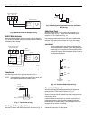
. When the Em Heat switch or a
thermostat
p
uts the
p
anel in the emer
g
enc
y
heat mode, the
heat
p
um
p
is locked out and calls for heat are sent to the E
terminal.
A heat
p
um
p
thermostat can also control emer
g
enc
y
heat
from the thermostat s
y
stem switch. An L terminal ener
g
ized
durin
g
the emer
g
enc
y
heat mode is re
q
uired. The
recommended heat
p
um
p
thermostats all have hot L
terminals. See Table 1.
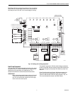
The two sta
g
e Em heat
j
um
p
er connects W2 and E. Jum
p
er
both
p
ins to ener
g
ize the W2 e
q
ui
p
ment on a call for
emer
g
enc
y
heat. When E is a different source of heat than
W2, remove the
j
um
p
er
(
for exam
p
le, two-sta
g
e heat
p
um
p
with electric heat stri
p
auxiliar
y
heat
)
. The
j
um
p
er is located
below the e
q
ui
p
ment terminals on the lower-left corner of the
p
anel.
Multi-Stage Thermostats
Use multi-sta
g
e thermostats to control two sta
g
es of heat via
W1 and W2 thermostat terminals. Control the third sta
g
e of
heat throu
g
h the sta
g
e timer built into the
p
anel. Control the
second sta
g
e of coolin
g
with the timer.
Manual and Automatic Changeover Thermostats
Automatic chan
g
eover thermostats
p
rovide automatic
chan
g
eover b
y
zone. Manual chan
g
eover thermostats heat or
cool based on the mode of each zone thermostat.
DIP Switch Number Status
1 Off
5 On
DIP Switch Number Status
1On
5Off
Table 4. Staging by Percentage of Zones Calling.
Number of
Zones in
System
Number of Zones Required
2nd Stage
Heat
3rd Stage
Heat
2nd Stage
Cool
32 32
42 33
52 43
63 54
73 54
83 65
94 75
10 4 7 6
11 4 8 6
12 5 9 7


