


TZ-3 TOTALZONE® ZONE CONTROL PANEL
68-0223-2 4
INSTALLATION
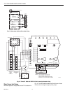
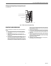
Mounting
CAUTION
Equipment Damage Hazard.
Do not mount TZ-3 inside HVAC equipment
Mount onl
y
on wall or on cold air return
1.
Mount the thermostats in each zone of the livin
g
s
p
ace
usin
g
the installation instructions
p
rovided with each
thermostat.
2.
Mount the dam
p
ers in the ductwork usin
g
the installa-
tion instructions
p
rovided with each dam
p
er.
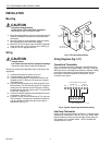
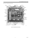
3.
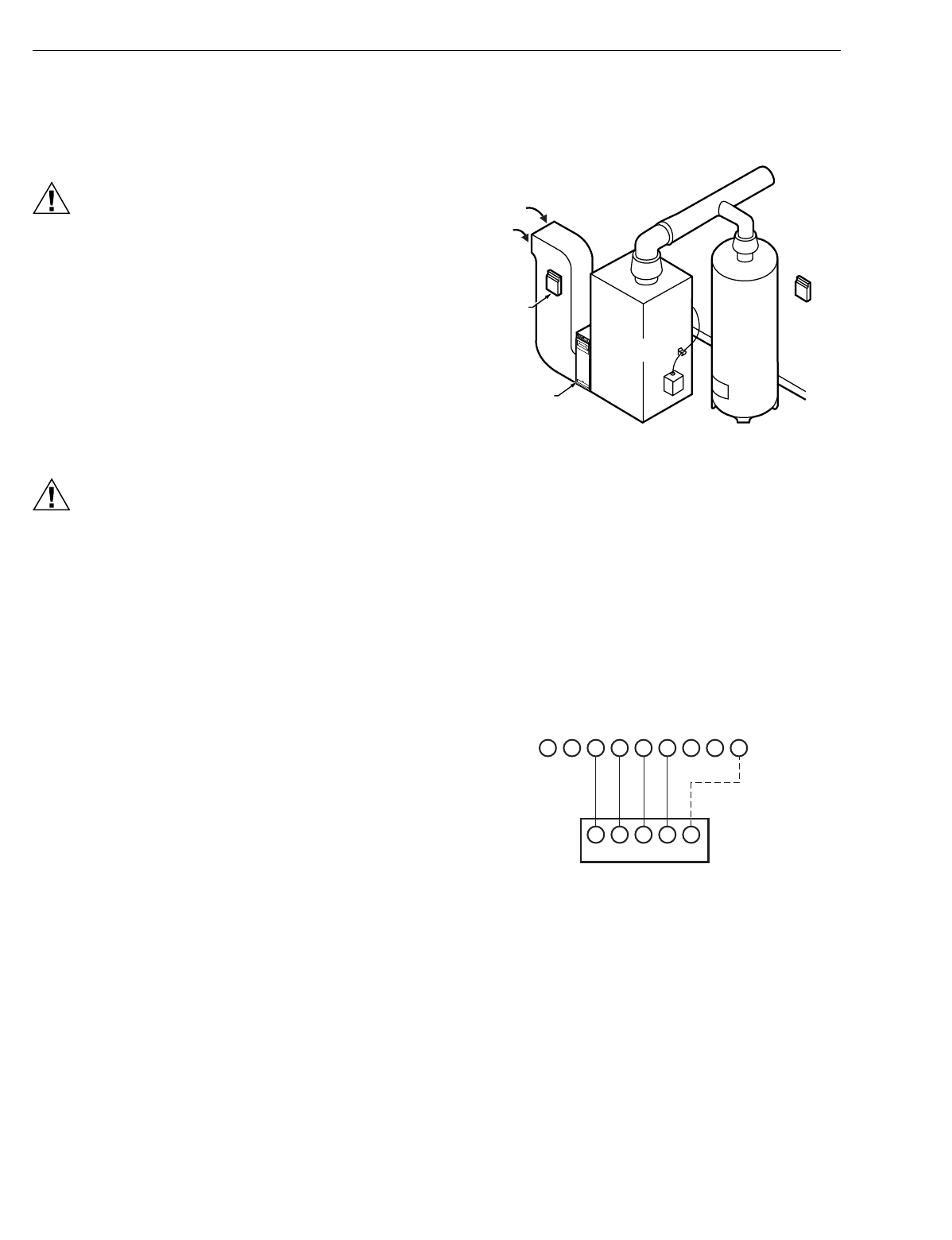
Mount the TZ-3 zone
p
anel near the HVAC e
q
ui
p
ment;
locate it on a wall or on the cold-air return. See Fi
g
. 2.
4.
Level the TZ-3 for a
pp
earance onl
y
.
Wiring
CAUTION
Voltage Hazard.
Can cause electrical shock or equipment damage.
Disconnect
p
ower before continuin
g
installation.
Wirin
g
must com
p
l
y
with a
pp
licable codes, ordinances, and
re
g
ulations.
1.
Connect thermostats as shown in Fi
g
. 3-5.
2.
Connect dam
p
ers as shown in Fi
g
. 6-10.
3.
Connect the Dischar
g
e Air Tem
p
erature Sensor
(
not
su
pp
lied
)
to the TL terminals.The wires are not
p
olar-
ized. See Fi
g
.12.
4.
Connect Add-A-Zone
p
anels
(
if used
)
to the AZ1 and
AZ2 terminals. The AZ1 terminal on the TZ-3 must be
wired to the AZ1 terminal on the TAZ
p
anel. Similarl
y
,
the AZ2 terminal must be wired on the TZ-3 to the AZ2
on the TAZ. See Fi
g
. 13.
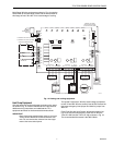
5.
Connect the HVAC e
q
ui
p
ment to the EQUIP terminals
on the
p
anel. See Fi
g
. 14-17.
6.
Connect a 40 VA, 24 volt transformer to TR1
(
hot
)
and
TR2
(
common
)
. This must be a dedicated transformer
and an
y
additional TAZ boards also each re
q
uire a
transformer. See Fi
g
. 11.
Fig. 2. TZ-3 mounting location.
Wiring Diagrams (Fig. 3-17)
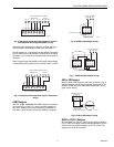
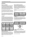
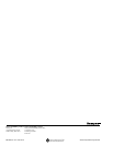
Conventional Thermostats
The C
(
common
)
terminal is used onl
y
on thermostats that
re
q
uire a common
(
for exam
p
le:T8601
)
. See Fi
g
. 3. Wire the
W2 terminal on a multi-sta
g
e thermostat
(
for exam
p
le: T8624
)
to the W2 on the
p
anel for second sta
g
e control from the
thermostat. If the thermostat has a Y2 terminal, do not
connect it to the
p
anel.
Fig. 3. Typical single-stage thermostat wiring.
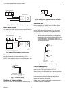
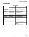
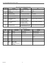
Heat Pump Thermostats
Select a heat
p
um
p
thermostat from Table 1. If the thermostat
selected has a se
p
arate Y1 and W1, see Fi
g
. 4. When usin
g
the thermostat to control the second sta
g
e of heat
(
W2
)
, set
DIP switch 5 to On, and DIP switch 1 to Off. Set both DIP
switches 6 and 7 to Off.
M19063
WATER
HEATER
T2-3
E
L
E
C
T
R
O
N
I
C
A
I
R
C
L
E
A
N
E
R
RETURN
AIR
T2-3
OPTIONAL
LOCATION
FURNACE
OR BOILER
HIGH
EFFICIENCY
AIR CLEANER
LW2 G Y R W M6
GYRWC
M4 M1
THERMOSTAT
ZONE CONNECTIONS ON PANEL
ZONE THERMOSTAT
M19064
MOTOR