


FocusPRO
™
TH6220D Programmable Thermostat
5
Installation Guide
4
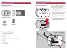
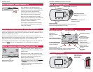
Wiring
1 Loosen screw terminals, insert
wires into terminal block, then
re-tighten screws.
2 Push excess wire back into the
wall opening. Keep wires in shaded
area as shown at left.
3 Plug the wall opening with non-
flammable insulation to prevent
drafts from affecting thermostat
operation.
Conventional
Heat Pump
NOTES
R & Rc terminals
In single-transformer system, leave metal
jumper in place between R & Rc. Remove
metal jumper if two-transformer system
.
C terminal
The C (common wire) terminal is optional
when thermostat is powered by batteries.
W (O/B) terminal
If thermostat is configured for a heat pump
in the Installer Setup, configure changeover
valve for cool (“O” factory setting) or heat
(“B”).
L terminal (Output)
Heat pump reset. L terminal powered contin-
uously when thermostat is set to Em Heat.
Configure thermostat for 2 heat / 1 cool heat
pump in the Installer Setup.
Wire specifications
Use 18- to 22-gauge thermostat wire.
Shielded cable is not required.
Keep wires in this
shaded area
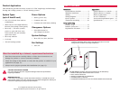
CAUTION: ELECTRICAL HAZARD. Can cause electrical shock or equipment damage.
Disconnect power before wiring.
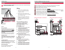
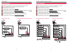
Wiring
Typical 1H/1C system: 1 transformer Typical 1H/1C system: 2 transformers
Remove
jumper
Wiring diagrams
Terminal Designations
Conventional Terminal Letters:
Y2 2nd stage compressor contactor
W2 2nd stage heat relay
G Fan relay
W 1st stage heat relay
C Common wire from secondary side of
cooling system transformer
Y 1st stage compressor contactor
R Heating power. Connect to secondary
side of heating system transformer.
Rc Cooling power. Connect to secondary
side of cooling system transformer.
Heat Pump Terminal Letters:
L Heat pump reset. L terminal powered
continuously when System is set to Em
Heat.
E Emergency heat relay
Aux Auxiliary heat relay
G Fan relay
O/B Changeover valve for heat pumps
C Common wire from secondary side of
cooling system transformer.
Y Compressor contactor
R Heating power. Connect to secondary
side of heating system transformer.
Rc Cooling power. Connect to secondary
side of cooling system transformer.
Power supply. Provide disconnect means and overload protection as required.
Factory-installed jumper. Remove for 2-transformer systems only.
Optional 24VAC common connection.
In Installer Setup, set system type to Heat Only
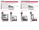
.
In Installer Setup, set system type to 1Heat/1Cool Heat Pump & changeover valve to 0 or B.
In Installer Setup, set system type to 2Heat/1Cool Heat Pump.
L terminal is powered continuously when thermostat is set to Em Heat.
Install field jumper between Aux and E if there is no emergency heat relay.
In Installer Setup, set system type to 2Heat/2Cool conventional.