


Installation Guide
4
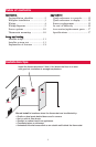
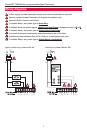
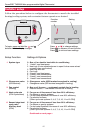
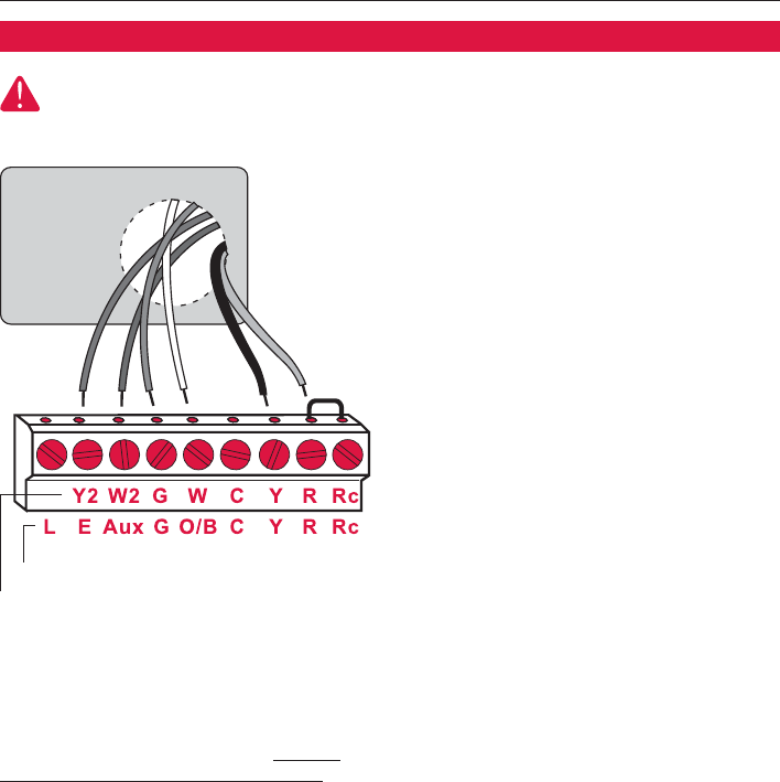
Wiring
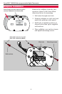
1 Loosen screw terminals, insert
wires into terminal block, then
re-tighten screws.
2 Push excess wire back into the
wall opening. Keep wires in shaded
area as shown at left.
3 Plug the wall opening with non-
flammable insulation to prevent
drafts from affecting thermostat
operation.
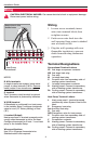
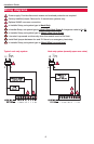
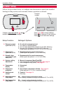
Conventional
Heat Pump
NOTES
R & Rc terminals
In single-transformer system, leave metal
jumper in place between R & Rc. Remove
metal jumper if two-transformer system
.
C terminal
The C (common wire) terminal is optional
when thermostat is powered by batteries.
W (O/B) terminal
If thermostat is configured for a heat pump
in the Installer Setup, configure changeover
valve for cool (“O” factory setting) or heat
(“B”).
L terminal (Output)
Heat pump reset. L terminal powered contin-
uously when thermostat is set to Em Heat.
Configure thermostat for 2 heat / 1 cool heat
pump in the Installer Setup.
Wire specifications
Use 18- to 22-gauge thermostat wire.
Shielded cable is not required.
Keep wires in this
shaded area
CAUTION: ELECTRICAL HAZARD. Can cause electrical shock or equipment damage.
Disconnect power before wiring.
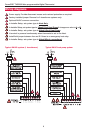
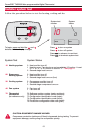
Wiring
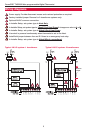
Terminal Designations
Conventional Terminal Letters:
Y2 2nd stage compressor contactor
W2 2nd stage heat relay
G Fan relay
W 1st stage heat relay
C Common wire from secondary side of
cooling system transformer
Y 1st stage compressor contactor
R Heating power. Connect to secondary
side of heating system transformer.
Rc Cooling power. Connect to secondary
side of cooling system transformer.
Heat Pump Terminal Letters:
L Heat pump reset. L terminal powered
continuously when System is set to Em
Heat.
E Emergency heat relay
Aux Auxiliary heat relay
G Fan relay
O/B Changeover valve for heat pumps
C Common wire from secondary side of
cooling system transformer.
Y Compressor contactor
R Heating power. Connect to secondary
side of heating system transformer.
Rc Cooling power. Connect to secondary
side of cooling system transformer.