


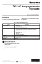
TH5110D NON-PROGRAMMABLE THERMOSTAT
69-1712—1 10
THERMOSTAT OPERATION
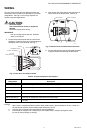
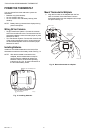
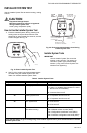
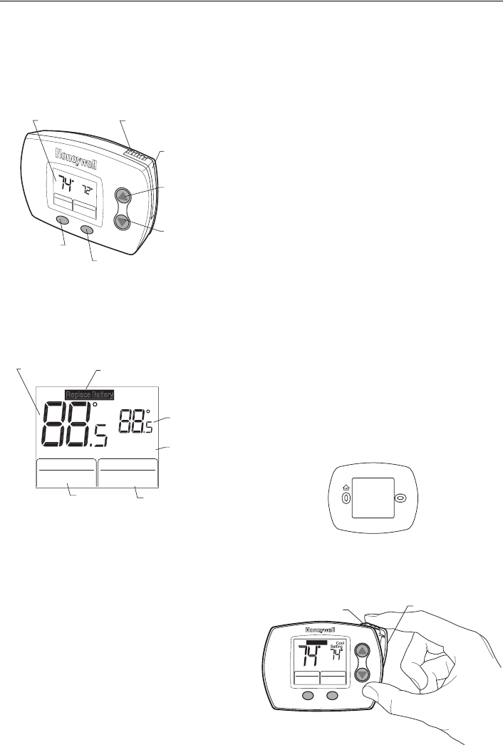
Thermostat Buttons and Battery Holder
See Fig. 21 for description of thermostat buttons and
battery holder.
Fig. 21. Review thermostat button description.
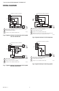
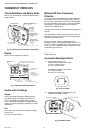
Display
See Fig. 22 for description of display.
Fig. 22. Review display description.
System and Fan Settings
System
Heat—Thermostat controls the heating system.
Off—Both heating and cooling systems are off.
Cool—Thermostat controls the cooling system.
Auto—Thermostat automatically changes between
heating and cooling operation, depending on indoor
temperature.
Fan
Auto —Fan runs only when the heating or cooling
system is on.
On—Fan runs continuously.
Minimum-Off Timer Compressor
Protection
The TH5110 has an adjustable Minimum-Off Timer that
can be set from zero to five minutes (Factory Setting—
five minutes). The Minimum-Off Timer can be bypassed
through the Installer System Test or it can be bypassed
permanently by setting the Minimum-Off Timer to 0
minutes in the Installer Setup.
The Minimum-Off Timer is activated after the compressor
turns off.
If the thermostat is system powered (common wire), the
Minimum-Off Timer is also activated upon initial startup
and after power interruptions.
If there is a call for cooling or heating during the
Minimum-Off Time, the thermostat flashes “Cool On” or
“Heat On”
a
. When the Minimum Off Timer expires, “Cool
On” or “Heat On”
a
appears solid in the display and the
compressor and fan turn on.
______________
a
Heat Pumps only.
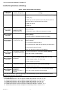
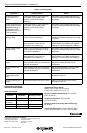
Accessories/Replacement Parts
1. Cover Plates (see Fig. 23):
50001137-001 (Small) Cover Plate—
4-5/16 in. (109 mm) high x
5-1/2 in. (140 mm) wide.
50002883-001(Large) Cover Plate—
6 in. (152 mm) high x
8-5/16 in. (211 mm) wide.
Fig. 23. Cover plate.
2. Replacement Battery Holder (see Fig. 24):
50000951-001 Battery Holder.
Fig. 24. Battery holder.
C
o
o
l
O
n
S
e
tti
ng
C
o
o
l
Inside
F
a
n
A
u
to
C
o
o
l
S
y
s
te
m
D
IGIT
A
L
D
ISPL
A
Y
F
AN
BU
TTO
N
SYSTE
M
BU
TTO
N
TE
M
PE
RA
T
UR
E
SETTI
N
G
BU
TTO
N
TE
M
PE
RA
T
UR
E
SETTI
N
G
BU
TTO
N
BA
TTE
R
Y
H
OL
D
E
R
BA
TTE
R
Y
H
OL
D
E
R
L
A
T
CH
M22084
PRESS TO RELEASE
BATTERY HOLDER
RAISES
TEMPERATURE
SETTING
TWO AAA
ALKALINE
BATTERIES
LOWERS
TEMPERATURE
SETTING
SELECTS HEAT, OFF, COOL OR AUTO
SELECTS AUTO OR ON
PRESS
Replace Battery
H
eat
C
oo
l
On
On
In
s
i
de
S
ettin
g
CoolH
ea
t
H
eat
Cool
AutoOff
Sy
ste
m
F
an
O
n Aut
o
INSIDE
TE
M
PERAT
U
R
E
TEMPERATURE
SETTING
INDICATES
THERMOSTAT IS
"CALLING" FOR
HEAT OR COOL
CURRENT
SYSTEM SETTING
M22083
CURRENT
FAN SETTING
INDICATES BATTERIES ARE
LO
W AND M
US
T BE REPLA
C
E
D
M22185
Replace Batter
y
Service Needed
In
s
i
de
C
oo
l
S
y
ste
m
F
an
A
u
t
o
BATTERY HOLDER
LATCH
BATTERY HOLDER
M22111