TB7100A1000 MULTIPRO™ MULTISPEED AND MULTIPURPOSE THERMOSTAT
5 63-2675—03
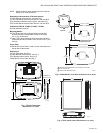
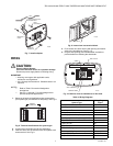
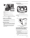
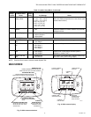
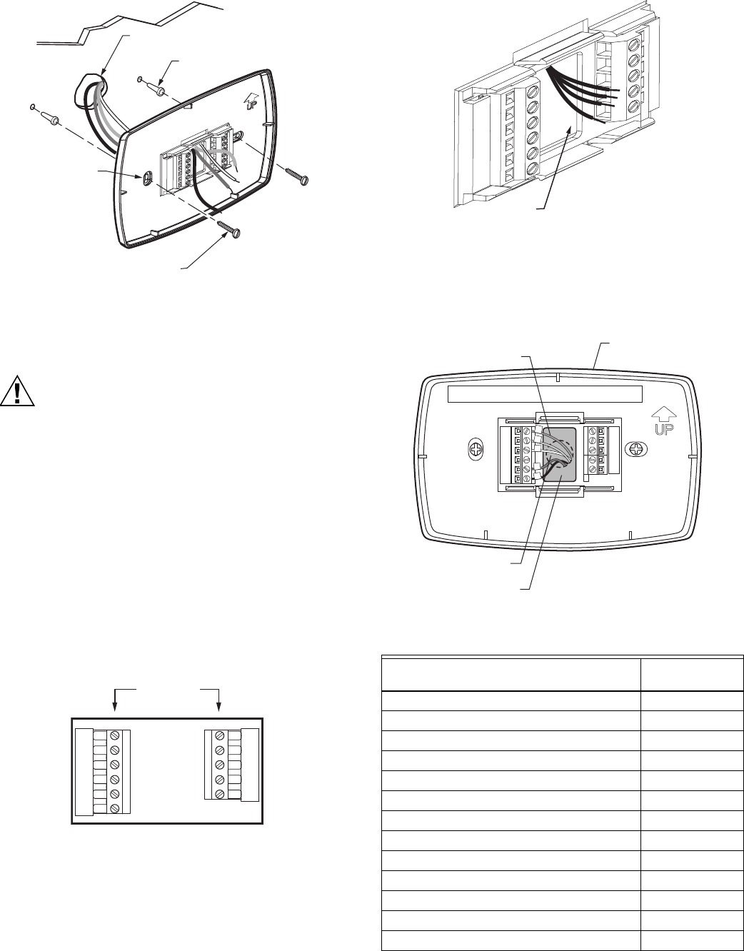
Fig. 7. Install wallplate.
WIRING
CAUTION
Electrical Shock Hazard.
Can cause electrical shock or equipment damage.
Disconnect power supply before connecting wiring.
IMPORTANT
— All wiring must agree with applicable codes,
ordinances and regulations.
— Use 18 gauge thermostat wire. Shielded cable is not
required.
NOTES:
— Refer to Table 5 for terminal designation
descriptions.
— See Fig. 11 through 17 for wiring diagrams for
specific equipment applications.
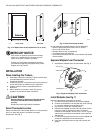
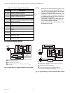
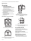
1. Select set of terminal identifications that correspond to
your system type (conventional or heat pump). See Fig. 8.
Fig. 8. Terminal identifications for system type.
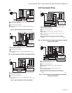
2. Loosen screw terminals used for the application.
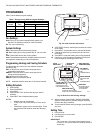
3. Insert the wires into the terminal block and tighten each
screw terminal. See Fig. 9.
Fig. 9. Insert wires into terminal block.
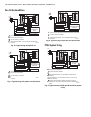
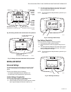
4. Push excess wire back into the wall opening and restrict
wires to the shaded area. See Fig. 10.
5. Plug the wall opening with nonflammable insulation to
prevent drafts from affecting the thermostat.
Fig. 10. Restrict wires to shaded area of wire hole.
Table 4. Wiring Diagrams.
WALL
MOUNTING
HOLES
M13665
MOUNTING
SCREWS (2)
WALL
ANCHORS (2)
WIRES THROUGH WALL
AND WIRE SLOT
M27415
C
G
Y
O/B
RC
R
W1
G2
G3
S1
S2
SCREW
TERMINALS
System Type
Wiring Diagram
Figure
Standard Heat/Cool (1H/1C) 11, 12
Heat Only 13
Heat Only with Fan 14
Cool only 15
Heat Pump (No Auxiliary Heat) (1H/1C) 16
Heat Pump (with Auxiliary Heat) (2H/1C) 17
4 Pipe Fan Coil 18
2 Pipe Fan Coil 19
2 Pipe Fan Coil with aux. heat 20
PTAC 1H/1C (High speed, Low speed fan) 21
PTAC 2H/1C (High speed, Low speed fan) 22
Multiple TR21 Sensors 25, 26, 27
Multiple C7189U Sensors 28
M13666
WIRE HOLE
WALLPLATE
M22266
WALL OPENING
WIRE
SHADED AREA


