TB7100A1000 MULTIPRO™ MULTISPEED AND MULTIPURPOSE THERMOSTAT
63-2675—03 18
a
If Installer Setup (0170) System Type is set to 2 pipe Fan Coil (8) or 2 pipe Fan Coil w/Aux Heat (9), the Y terminal will be used
for cooling and heating. If Installer Setup (0170) System Type is set to 4 pipe Fan Coil (7), the Y terminal will be used for cooling
only.
b
When fan is in AUTO, it automatically selects the fan speed based on how far away the temperature is from the setpoint.
c
If Installer Setup (0170) System Type is set to 2 pipe Fan Coil with Auxiliary Heat (9), the W1 terminal will be used for reheat. If
Installer Setup (0170) System Type is set to 4 pipe Fan Coil (7),the W1 terminal will be used for heating.
a
When the fan is in AUTO, it automatically selects the fan speed based on how far away the temperature is from the setpoint.
b
Configure O/B in Installer Setup. Based on last piece of equipment called (cooling=O; heating=B).
c
If Installer Setup (1070) System Type is set to 2Heat/1 Cool PTAC.
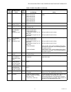
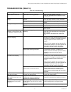
Table 10. Sequence of Operations for Fan Coil Systems.
System Setting Fan Setting Call for Action Energize Terminals Screen Message
Off/Cool/Heat/Em Heat/Auto Auto -- --
Cool or Auto Auto 4 Pipe Cooling
Y, G
b
, G2
b
, G3
b
Cool On
Cool or Auto LO 4 Pipe Cooling Y, G Cool On
Cool or Auto MED 4 Pipe Cooling Y, G2 Cool On
Cool or Auto HIGH 4 Pipe Cooling Y, G3 Cool On
Heat or Auto Auto 4 Pipe Heating
W1
c
, G
b
, G2
b
, G3
b
Heat On
Heat or Auto LO 4 Pipe Heating
W1
c
, G
Heat On
Heat or Auto MED 4 Pipe Heating
W1
c
, G2
Heat On
Heat or Auto HIGH 4 Pipe Heating
W1
c
, G3
Heat On
Cool or Heat Auto
2 Pipe Cooling/Heating
a
Y
a
, G
b
, G2
b
, G3
b
Cool On or Heat On
Cool or Heat LO
2 Pipe Cooling/Heating
a
Y
a
, G
Cool On or Heat On
Cool or Heat MED
2 Pipe Cooling/Heating
a
Y
a
, G2
Cool On or Heat On
Cool or Heat HIGH
2 Pipe Cooling/Heating
a
Y
a
, G3
Cool On or Heat On
Em Heat Auto 2 Pipe Call for Auxiliary Heat
Y
a
, W1
c
, G
b
, G2
b
, G3
b
Heat On
Em Heat LO 2 Pipe Call for Auxiliary Heat
Y
a
, W1
c
, G
Heat On
Em Heat MED 2 Pipe Call for Auxiliary Heat
Y
a
, W1
c
, G2
Heat On
Em Heat HIGH 2 Pipe Call for Auxiliary Heat
Y
a
, W1
c
, G3
Heat On
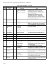
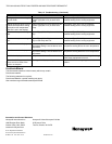
Table 11. Sequence of Operations for PTAC Systems.
System Setting Fan Setting Call for Action Energize Terminals Screen Message
Off/Cool/Heat/
Em Heat/Auto
Auto --
O/B
b
--
Cool or Auto Auto Stage 1 Cooling
Y, G
a
, G3
a
, O/B
b
Cool On
Cool or Auto LO Stage1 Cooling
Y, G, O/B
b
Cool On
Cool or Auto HIGH Stage 1 Cooling
Y, G3, O/B
b
Cool On
Heat or Auto Auto Stage 1 Heating
Y, G
a
, G3
a
, O/B
b
Heat On
Heat or Auto LO Stage 1 Heating
Y, G, O/B
b
Heat On
Heat or Auto HIGH Stage 1 Heating
Y, G3, O/B
b
Heat On
Em Heat Auto Stage 1 and 2 Heating
Y, W1
c
, G
a
, G3
a
, O/B
b
Heat On
Em Heat LO Stage 1 and 2 Heating
Y, W1
c
, G, O/B
b
Heat On
Em Heat HIGH Stage 1 and 2 Heating
Y, W1
c
, G3, O/B
b
Heat On


