


TB7100A1000 MULTIPRO™ MULTISPEED AND MULTIPURPOSE THERMOSTAT
11 62-0273—05
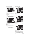
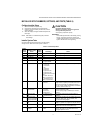
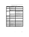
0 3 4 9 A u t o Fa n R e se t 0 0 — I n a c ti v e
1—Reset back to Auto
after 2 hours
2—Reset back to Auto
after 4 hours
The timer will be set after the user selects the
constant fan speed. Fan will be set to Auto
automatically when time out. The start time is
calculated after initial call for heat/cool is satisfied,
then 2 hour timing begins.
The timer will be set after the user selects the
constant fan speed. Fan will be set to Auto
automatically when time out. The start time is
calculated after initial call for heat/cool is satisfied,
then 4 hour timing begins. Only available for fan
coil or PTAC applications.
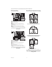
0535 Temporary
Occupied Duration
Limit
3 0–12 hours 0 means no limit.
0540 Number of Periods 4 2—2 Periods
4—4 Periods
Does not appear if Non-programmable is chosen
(ISU 0160).
Applies to all days of the week. If 2 is selected the
Cancel Period option will not appear on the
display.
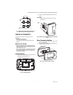
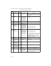
0580 Minimum
Compressor Off
Time
50—Off
2—2 minutes
3—3 minutes
4—4 minutes
5—5 minutes
Only shown if system has cool stages in CNV,
Heat Pump, PTAC (ISU 0170).
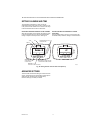
0600 Heat Temperature
Range Stops
90 40 to 90°F (4 to 32°C) Only shown if system has heat stages (ISU 0170).
0610 Cool Temperature
Range Stops
50 50 to 99°F (10 to 37°C) Only shown if system has cool stages (ISU 0170).
0640 Clock Format 12 12—12 Hour
24—24 Hour
0650 Extended Fan-on
time Heat
00—Off
90—90 seconds
Not displayed if fan set to fossil or cool only
systems (ISU 0170)
0660 Extended Fan-on
time Cool
00—Off
40—40 seconds
Only shown if system has cool stages. (ISU 0170)
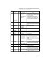
0670 Keypad Lockout 0 0—Unlocked
1—Partial Lockout 1
2—Partial Lockout 2
3—Partial Lockout 3
4—Fully Locked
Unlocked: All functions accessible.
Partial 1: Locks out schedule and system
changes.
Partial 2: Locks out schedule, system, and fan
changes.
Partial 3: Locks out schedule, system, fan, and up/
down arrow changes.
Full: Entire interface locked/non-functional.
0680 Temperature
Control Heat
2 1—Less Aggressive
2—Standard
3—More Aggressive
Only shown if system has heat stages (ISU 0170).
Only integral gains are affected by this setting. The
setting affects control operation in all control
regimes (not just recovery or setpoint change).
0685 Recovery Heat
Ramp Rate
5 0-20°F/hour Only shown if system has heat stages (ISU 0170).
0 disables the ramped recovery (step setpoint
change at period start time).
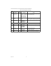
0690 Temperature
Control Cool
2 1—Less Aggressive
2—Standard
3—More Aggressive
Only shown if system has cool stages (ISU 0170).
Only integral gains are affected by this setting. The
setting affects control operation in all control
regimes (not just recovery or setpoint change).
0695 Recovery Cool
Ramp Rate
3 0-20°F/hour Only shown if system has cool stages (ISU 0170).
0 disables the ramped recovery (step setpoint
change at the period start time).
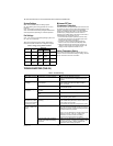
Table 4. Installer Setup Menu. (Continued)
Installer
Setup
Number
Installer Setup
Name
Default
Setting All Settings Notes