


T8602D CHRONOTHERM® IV PROGRAMMABLE THERMOSTATS
69-1510-4 2
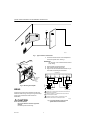
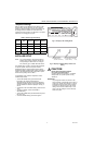
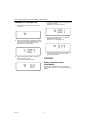
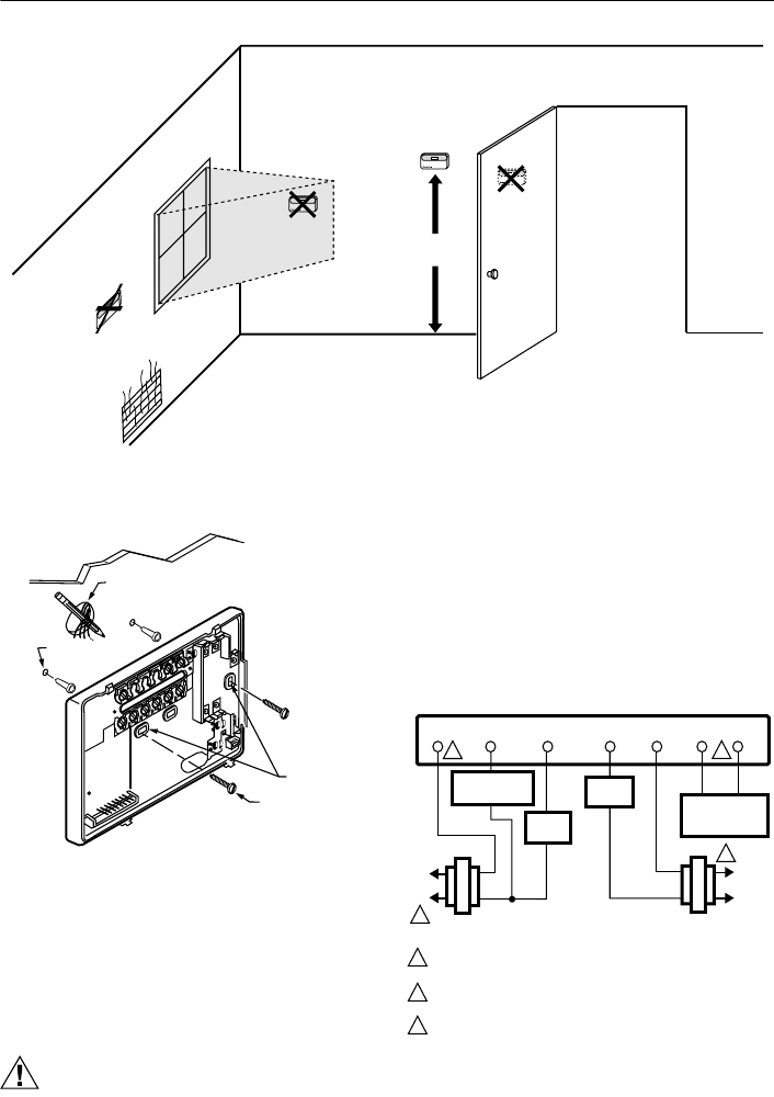
Fig. 1. Typical location of thermostat.
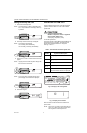
Fig. 2. Mounting the wallplate.
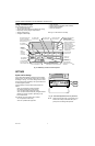
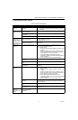
WIRING
All wiring must comply with local electrical codes and
ordinances. Refer to Fig. 3 through 6 for typical hookups.
A letter code is located near each terminal for
identification.
CAUTION
Electrical Hazard.
Can cause electrical shock or equipment
damage.
Disconnect power before wiring.
1. Loosen the terminal screws on the wallplate and
connect the system wires. See Fig. 7.
IMPORTANT
Use 18 gauge, color-coded thermostat cable for
proper wiring.
2. Securely tighten each terminal screw.
3. Push excess wire back into the hole.
4. Plug the hole with nonflammable insulation to pre-
vent drafts from affecting the thermostat.
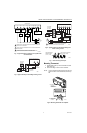
Fig. 3. Typical hookup in heat and cool
system with two transformers.
1.5 METERS
(5 FEET)
YES
NO
NO
NO
M10856
WIRES
THROUGH WALL
WALL
MOUNTING
HOLES
M15044
MOUNTING
SCREWS
WALL
ANCHORS (2)
L1
(HOT
)
L2
M10855
FAN
RELAY
YG
THERMOSTAT
RC
HEAT
RELAY
RW
L
1
(
HOT)
L
2
COMPRESSOR
CONTACTOR
HEATING
TRANSFORMER
COOLING
TRANSFORMER
2
1
POWER SUPPLY. PROVIDE DISCONNECT MEANS AND OVERLOAD
PROTECTION AS REQUIRED.
JUMPER RC TERMINAL TO R TERMINAL WHEN INSTALLED ON A
ONE TRANSFORMER SYSTEM.
AVAILABLE ON SELECT MODELS. OT WIRES MUST HAVE A
SEPARATE CABLE FROM THE THERMOSTAT CABLE.
2
1
1
3
OTOT
OUTDOOR
TEMPERATURE
SENSOR
3