


T8000C, T8001C AND T8024D PROGRAMMABLE THERMOSTATS
68-0195–2
4
M12202
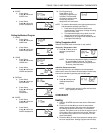
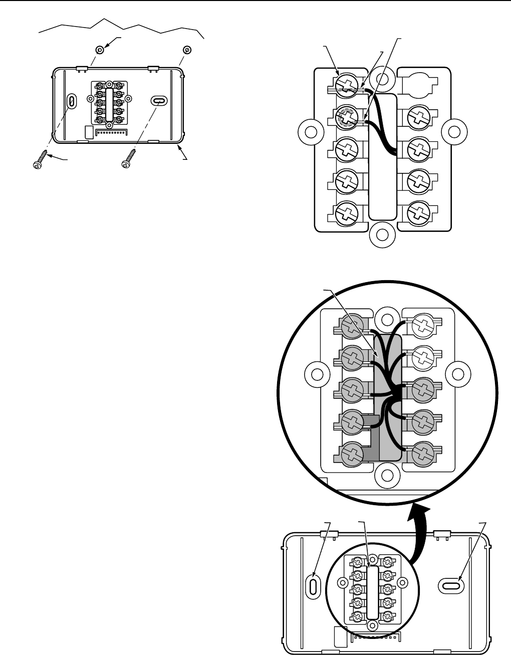
WALL
WALL
ANCHORS (2)
WALLPLATE
MOUNTING
SCREWS (2)
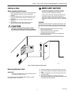
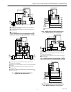
Fig. 3. Mounting wallplate to wall.
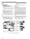
Wiring
IMPORTANT
Use an 18-gauge maximum wire for wiring the
thermostats.
All wiring must comply with local electrical codes and
ordinances. Disconnect the power supply to prevent electrical
shock or equipment damage.
The shape of the terminals permits insertion of straight or
wraparound wiring connections; either method is acceptable.
A letter code is located near each terminal for identification.
See Fig. 4.
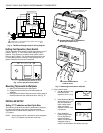
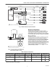
NOTE: To ensure proper mounting of thermostat, restrict all
wiring to the shaded area in the center of the
terminals. See Fig. 5.
The T8000C Thermostats are powered through the heating/
cooling system controls and are adaptable to most 18 to 30
Vac heating-cooling systems.
The T8001C and T8024D Thermostats are powered directly
from the system transformer. The T8001C Thermostats are
adaptable to most 18 to 30 Vac single-stage heating/cooling
systems and the T8024D is adaptable to multistage systems.
All T8001C and T8024D thermostats require a common wire
connected to the system transformer to operate properly.
Refer to Fig. 6 through 10 for typical wiring hookups.
KEEP WIRING IN
SHADED AREA
MOUNTING
SCREW HOLE
MOUNTING
SCREW HOLE
WIRING ENTRANCE
HOLE
M18503
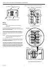
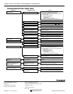
G
C
R
Y
W1
W2
B
O
Fig. 8. T8000C wiring diagram in heat-cool
system with two transformers.
TERMINAL
SCREW
M20212
G
R
C
Y
W1
B
O
FOR STRAIGHT
INSERTION STRIP
5/16 IN. (8 MM)
FOR WRAPAROUND
STRIP 7/16 IN. (11 MM)
Y2
W2
Fig. 4. Wiring connections.
Fig. 5. Restrict wiring to shaded area.