T8000C, T8001C AND T8024D PROGRAMMABLE THERMOSTATS
68-0195–2
11
L1
(HOT)
L2
1
1
POWER SUPPLY. PROVIDE DISCONNECT MEANS AND OVERLOAD PROTECTION AS REQUIRED.
SYSTEM
SWITCH
FAN
SWITCH
HEAT
OFF
COOL
O
G
B
R
W
Y
FAN RELAY
M11731
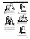
THERMOSTAT WALLPLATE SYSTEM COMPONENTS
HEAT RELAY
HEAT CHANGEOVER
RELAY
COOL CHANGEOVER
RELAY
COMPRESSOR
RELAY
ON
AUTO
POWER
SUPPLY
LOGIC/
CONTROL
CIRCUIT
EF
FUEL
SWITCH
STAGE 1
HEAT OR
COOL
C
K1
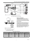
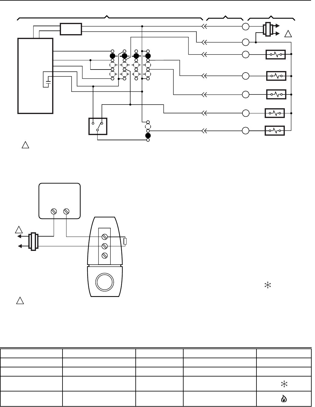
Fig. 16. T8001C hardwired internal schematic.
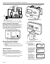
Fig. 17. Connect resistor to the TACO zone
valve terminal numbers 1 and 2.
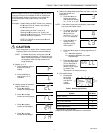
FAN Switch Settings SYSTEM Switch Settings Call for Action Energize Terminals Display Icons
Auto Off None None None
On Any Any G None
Auto Cool Cooling G,Y
Auto Heat Heating W,G
a
1
2
3
RESISTOR
L1
(HOT)
L2
1
1
THERMOSTAT
RW
POWER SUPPLY. PROVIDE DISCONNECT MEANS AND
OVERLOAD PROTECTION AS REQUIRED.
TACO ZONE VALVE
M11677
Sequence of Operations
The Fan, Heat and Cool outputs are relay or mosfet
controlled. A loss of ac power or a change in the SYSTEM
switch setting can cause the outputs to turn off. The truth
table shows the sequence of operations for the FAN settings
and SYSTEM modes. See Table 3, Sequence of Operations.
Minimum Off-Timer
A minimum off-timer in the T8000C and T8001D assures that
the compressor does not come on again for at least five
minutes after it turns off. The minimum off-timer is triggered
when the compressor turns off and when the SYSTEM switch
position is changed. If the compressor turns off when the
setpoint is changed, the minimum off-timer is triggered. Power
interruption and power restoration also trigger the minimum off-
timer. The minimum off-timer operates in cooling on the
T8000C and T8001C. A flashing snowflake indicates the
minimum off-timing is in effect.
Table 3. Sequence of Operations.
a
When the Fuel switch is in the E position.


