


69-1204
5
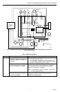
ST7997 OIL BURNER MOUNTED ELECTRIC FAN TIMER
N
HUM
N
N
MED LO
LO
HI
BLACK
RED
WHITE
VIOLET
N
OIL
PRIMARY
L1
L1
L2
L2
BURNER/
VALVE
HUMIDIFIER EAC
L2
THERMOSTAT
5-WIRE
COMPRESSOR
CONTACTOR
RC
RC
F1
ISOLATION
HEAT CALL
CONTROL
ELECTRONICS
LIMIT
RC
W
R
C
C
G
Y
G
Y
G
Y
L1
GND
SCREW TERMINAL
1/4 IN. QUICK CONNECT
CIRCULATOR
BLOWER
LIMIT
(LINE
VOLTAGE)
ORANGE
R7997
INTEGRATED
OIL PRIMARY
WITH BLOWER
DELAY
OIL
VALVE
AIR FLOW
SWITCH
BURNER
MOTOR
POWER
VENT
MOTOR
J-BOX
M12923
OEFT
ST7997
K1 K2
EAC
N
1K2
1K1
2K2
2K1
COOL
HEAT
MED HI
CONTINUOUS
FURNACE
LIMIT
TT
UNUSED
WIRES
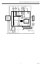
Fig. 5. ST7997 Oil Burner Mounted Electronic Fan Timer airflow switch and power vent motor for
power venting wiring.
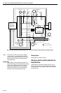
Table 1. ST7997 Wiring Options.
Mode Action System Response
OPTIONS
Constant circulating fan is
connected. (Optional connectors are
available for separate circulating fan
speed tap.)
a. Circulating fan is energized at low speed when there is
no call for heat, cool or fan.
b. If fan operation is required by a call for heat, cool or
fan, the ST7997 switches off the continuous fan speed
tap before energizing the other fan speed.
Electronic air cleaner is connected.
(Optional connectors are available
for 120 Vac electronic air cleaner.)
Electronic air cleaner (EAC) connections are energized when
the heat or cool speed of the circulating fan is energized.
EAC connections are not energized when the optional
continuous fan terminal is energized.
NOTE: If continuous fan option is selected, connect EAC
to line voltage input (L1).
Humidity control is connected.
(Optional connectors are available
for 120 Vac humidifier.)
Humidifier connections are energized when burner motor is
energized on standard models and when oil valve is
energized on purging models.