


69-1204
4
ST7997 OIL BURNER MOUNTED ELECTRIC FAN TIMER
N
HUM
N
N
COOL
HEAT
MED LO
LO
HI
BLACK
RED
WHITE
VIOLET
N
OIL
PRIMARY
L1
L1
L2
L2
BURNER/
VALVE
HUMIDIFIER EAC
L2
THERMOSTAT
5-WIRE
COMPRESSOR
CONTACTOR
RC
RC
F1
ISOLATION
HEAT CALL
CONTROL
ELECTRONICS
LIMIT
RC
W
R
C
C
G
Y
G
Y
G
Y
L1
GND
SCREW TERMINAL
1/4 IN. QUICK CONNECT
CIRCULATOR
BLOWER
LIMIT
(LINE
VOLTAGE)
ORANGE
R7997
INTEGRATED
OIL PRIMARY
WITH BLOWER
DELAY
OIL
VALVE
BURNER
MOTOR
J-BOX
M12922
OEFT
ST7997
K1 K2
EAC
N
1K2
1K1
2K2
2K1
COOL
HEAT
MED HI
CONTINUOUS
FURNACE
LIMIT
TT
UNUSED
WIRES
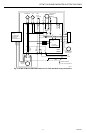
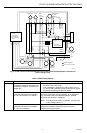
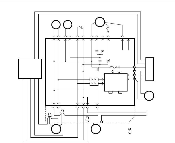
Fig. 4. ST7997 Oil Burner Mounted Electronic Fan Timer wiring for units with pre- and post purge.
NOTE: Two dummy quick connect terminals, labeled
“unused wires”, not connected to the ST7997
circuitry, are provided on the back of the case to
hold unused wires from the circulation blower
motor speed taps.
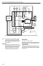
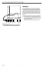
IMPORTANT
Field changes to the speeds (low, medium low,
medium high, high) of the ST7997 blower modes
(heat, cool, or continuous fan) can be made to
models using Molex® connectors by cutting
speed wires and splicing in an unused lead in
accordance with local and national codes.
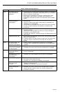
Wiring Options
Wiring options are listed in Table 1.
Setting the Heat Fan-Off and Heat Fan-On
Delay Switches
Set the Heat Fan-Off delay switches to 60, 90, 120 or
150 seconds. See Fig. 6. The off delay time starts when
the burner motor is de-energized at the end of a thermo-
stat call for heat.