69-1204
2
ST7997 OIL BURNER MOUNTED ELECTRIC FAN TIMER
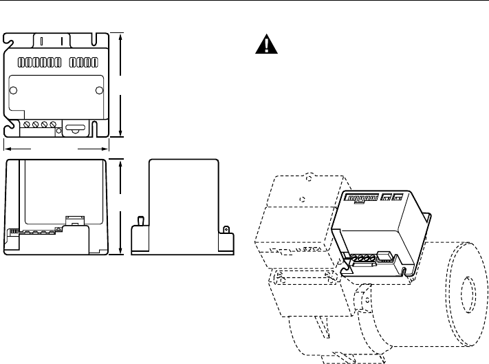
Fig. 1. ST7997A,B Oil Burner Mounted Electric Fan
Timer dimensions in in. (mm).
Mounting:
Mounts directly on standard 4 in. (102 mm) by 4 in.
(102 mm) junction box.
Packaging:
Unit pack and bulk pack.
Connections:
R7997, Oil Burner Motor, Oil Valve and Power (L1, L2):
Six (6) 1/4 in. (6 mm) by 1/32 in. (0.8 mm) quick
connects pass through recessed cover on bottom of
case.
Circulator Blower (Neutral, Heat, Cool, Continuous),
Limit (Hot, Limit): One six-position Molex® in-line
connector flush with top of case or six 1/4 in. (6 mm)
by 1/32 in. (0.8 mm) quick connects individually
recessed in top of case.
Humidifier: Two 1/4 in. (6 mm) by 1/32 in. (0.8 mm)
quick connects individually recessed in top of case.
Electronic Air Cleaner: Two 1/4 in. (6 mm) by 1/32 in.
(0.8 mm) quick connects individually recessed in top
of case.
Thermostat/Cooling Contactor: Four No. 4 screw
terminals marked Rc, Y, G and C on front side of
case.
INSTALLATION
When Installing this Product...
1. Read these instructions carefully. Failure to follow
them can damage the product or cause a hazardous
condition.
2. Check the ratings and specifications given in the
instructions and on the product to make sure the
product is suitable for your application.
3. Installer must be a trained, experienced service
technician.
4. After installation is complete, check out the product
operation as provided in these instructions.
C
M12920
YGRc
4-9/32 (109)
4-1/4
(108)
3-27/32
(97)
WARNING
Electrical Shock Hazard
Can cause serious injury or death.
Disconnect power supply before wiring to prevent
electrical shock or equipment damage.
Location and Mounting
Mount the ST7997 on the oil burner 4 in. (102 mm) by 4 in.
(102 mm) junction box compartment using four No. 6
screws (obtained locally). See Fig. 2.
ST7997R7997
BURNER
M12919
Fig. 2. ST7997A,B Oil Burner Mounted Electric Fan
Timer typical installation.
IMPORTANT
The ST7997 requires a mechanical or electronic
(power-stealing or battery-powered) five-wire
thermostat with independent heat/cool circuits
(R, W, Rc, Y, G).
Wiring
All wire must comply with local codes and ordinances.
Refer to Fig. 3 for standard wiring connections and Fig. 4
for units with pre- and post purge.
Make wiring connections within the oil burner junction box
for applications requiring power-venting. Add a 4 in. by
4 in. (102 mm by 102 mm) junction box, at least 1/2 in.
(13 mm) deep between the ST7997 and the oil burner
junction box. See Fig. 5 for wiring diagram showing airflow
switch and power vent motor.


