


Français : voir la page 21 • Español: vea la página 41
17 69-2091EFS—07
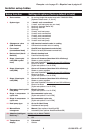
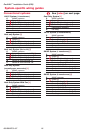
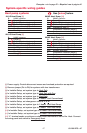
System-specific wiring guides
Heat pump systems
See [notes] below.
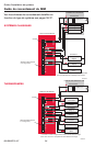
1H/1C Heat Pump [8]
C 24VAC common
R Power [1]
Rc [R+Rc+Rh joined by jumper]
Rh [R+Rc+Rh joined by jumper]
O/B Changeover valve [7]
Y Compressor contactor
G Fan relay
2H/1C Heat Pump [9]
C 24VAC common
R Power [1]
Rc [R+Rc+Rh joined by jumper]
Rh [R+Rc+Rh joined by jumper]
O/B Changeover valve [7]
Aux Auxiliary heat relay
Y Compressor contactor
G Fan relay
L Relay [12]
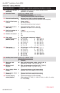
2H/2C Heat Pump [10]
C 24VAC common
R Power [1]
Rc [R+Rc+Rh joined by jumper]
Rh [R+Rc+Rh joined by jumper]
O/B Changeover valve [7]
Y Compressor contactor (stage 1)
Y2 Compressor contactor (stage 2)
G Fan relay
3H/2C Heat Pump [11]
C 24VAC common
R Power [1]
Rc [R+Rc+Rh joined by jumper]
Rh [R+Rc+Rh joined by jumper]
O/B Changeover valve [7]
Aux Auxiliary heat relay
Y Compressor contactor (stage 1)
Y2 Compressor contactor (stage 2)
G Fan relay
L Relay [12]
[1] Power supply. Provide disconnect means and overload protection as required.
[2] Remove jumper (Rc to Rh) for systems with two transformers.
[3] In Installer Setup, set system type to Heat Only.
[4] In Installer Setup, set system type to Heat Only with Fan.
[5] In Installer Setup, set system type to Cool Only.
[6] In Installer Setup, set system type to 2 Heat/2 Cool Conventional.
[7] In Installer Setup, set changeover valve to O or B.
[8] In Installer Setup, set system type to 1 Heat/1 Cool Heat Pump.
[9] In Installer Setup, set system type to 2 Heat/1 Cool Heat Pump.
[10] In Installer Setup, set system type to 2 Heat/2 Cool Heat Pump.
[11] In Installer Setup, set system type to 3 Heat/2 Cool Heat Pump.
[12] “L” terminal sends a continuous output when thermostat is set to Em. Heat. Connect
to zoning panel and switch to Emergency Heat.