


RedLINK
TM
Installation Guide (EIM)
69-2091EFS—07 16
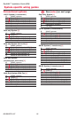
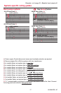
System-specific wiring guides
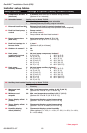
Conventional systems
See [notes] on next page.
1H/1C System (1 transformer)
C 24VAC common
R Power [1]
Rc [R+Rc+Rh joined by jumper]
Rh [R+Rc+Rh joined by jumper]
W Heat relay
Y Compressor contactor
G Fan relay
Heat-only System [3]
C 24VAC common
R Power [1]
Rc [R+Rc+Rh joined by jumper]
Rh [R+Rc+Rh joined by jumper]
W Heat relay
Heat-only System (Series 20) [3]
C 24VAC common
R Series 20 valve terminal "R" [1]
Rc [R+Rc+Rh joined by jumper]
Rh [R+Rc+Rh joined by jumper]
W Series 20 valve terminal "B"
Y Series 20 valve terminal “W”
Heat-only System
(normally open zone valve) [3]
C 24VAC common
R Power [1]
Rc [R+Rc+Rh joined by jumper]
Rh [R+Rc+Rh joined by jumper]
Y Normally open zone valve
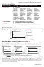
Heat Only System With Fan [4]
C 24VAC common
R Power [1]
Rc [R+Rc+Rh joined by jumper]
Rh [R+Rc+Rh joined by jumper]
W Heat relay
G Fan relay
Cool Only System [5]
C 24VAC common
R Power [1]
Rc [R+Rc+Rh joined by jumper]
Rh [R+Rc+Rh joined by jumper]
Y Compressor contactor
G Fan relay
1H/1C System (2 transformers)
C 24VAC common
R Power [1]
Rc Power (cooling) [1, 2]
Rh Power (heating) [1, 2]
W Heat relay
Y Compressor contactor
G Fan relay
2H/2C System (1 transformer) [6]
C 24VAC common
R Power [1]
Rc [R+Rc+Rh joined by jumper]
Rh [R+Rc+Rh joined by jumper]
W Heat relay (stage 1)
W2 Heat relay (stage 2)
Y Compressor contactor (stage 1)
Y2 Compressor contactor (stage 2)
G Fan relay
2H/2C System (2 transformers) [6]
C 24VAC common
R Power [1]
Rc Power (cooling) [1, 2]
Rh Power (heating) [1, 2]
W Heat relay (stage 1)
W2 Heat relay (stage 2)
Y Compressor contactor (stage 1)
Y2 Compressor contactor (stage 2)
G Fan relay