


R8182D,E,F,H,J COMBINATION PROTECTORELAY™ AND HYDRONIC HEATING CONTROLS
7 68-0105—2
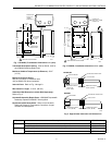
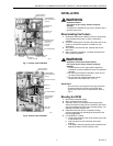
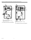
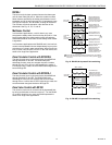
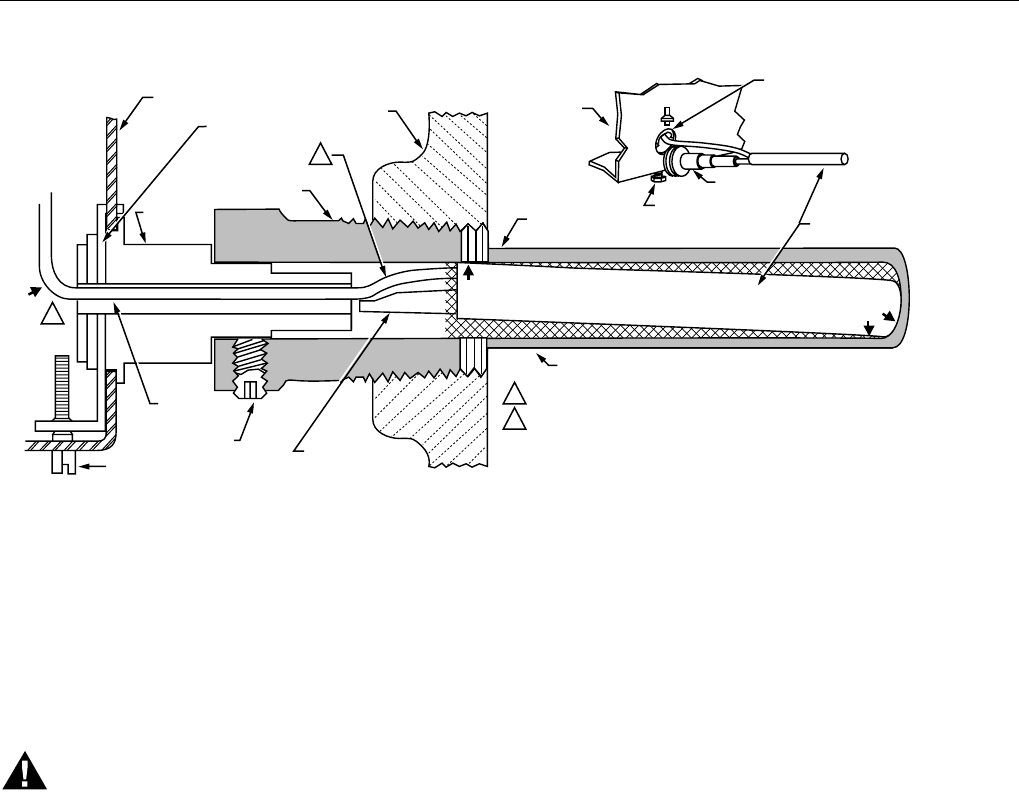
Fig. 9. Positioning the sensing bulb in the immersion well.
WIRING
IMPORTANT
Use Underwriters Laboratories Inc. listed connectors
when making external circuit connections to the
orange and white line voltage burner and ignition
leadwires of the R8182H,J.
WARNING
Electrical Shock Hazard.
Can cause severe injury, death or property
damage.
Disconnect power supply before wiring to prevent
electrical shock or equipment damage.
All wiring must comply with local codes, regulations, and
ordinances.
IMPORTANT
Terminals on the R8182 are approved for copper
wire only.
Follow the wiring instructions furnished by the appliance
manufacturer, if available, or refer to Fig. 11 through 17. For
wiring multiple zoning systems, refer to Fig. 16 and 17.
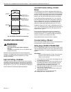
The R8182 is equipped with special wiring terminals. Wires
can be wrapped around the terminal screw or inserted from
the side.
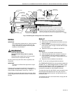
Method 1
1. Strip 7/16 in. of insulation from the wire end.
2. Wrap the wire 3/4 of the distance around the screw as
shown in method 1.
3. Using a standard, flat-headed screwdriver, tighten the
screw until the wipe is snugly in contact with the screw
and contact plate.
4. Tighten the screw pin an additional one-half turn.
Method 2
1. Strip 5/16 in. of insulation from the wire end.
2. Insert wire beneath the screw as shown in method 2.
3. Using a standard, flat-heat screwdriver, tighten the
screw until the wire is snugly in contact with the screw
and contact plate.
4. Tighten the screw an additional one-half turn.
NOTE: Do not use a push-type ratchet screwdriver.
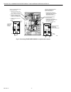
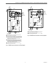
The TRADELINE® R8182D,H can be converted to replace an
R8182B,C,E,F or a White Rodgers 6C92-2 or 6C92-3. When
replacing a White Rodgers model, the immersion well must
also be replaced. Refer to Fig. 10 for Aquastat® limit
connections necessary for each R8182D conversion.
To release the wires from the R8182, insert a screwdriver into
the rectangular hole adjacent to the wire, push inward to
release the locking-grip on the wire, and pull the wire out of
the terminal hole.
To reinsert the wire into a new terminal hole, simply push the
wire into the new slot.
CONTROLLER
CASE
IMMERSION
WELL CLAMP
ADAPTER
IMMERSION
WELL SPUD
BOILER
OLD IMMERSION
WELL ASSEMBLY
BACK OF
CONTROLLER
CASE
IMMERSION
WELL CLAMP
SCREW
ADAPTER
SENSING
BULB
HEAT-CONDUCTIVE COMPOUND
SETSCREW
CAPILLARY
TUBE
(
C)
IMMERSION
WELL CLAMP
IMMERSION
WELL CLAMP SCREW
SHORT TUBE
FITS IN CENTRAL
RECESS OF ADAPTER
BEND THE CAPILLARY TUBE TO HOLD THE SENSING BULB IN GOOD
THERMAL CONTACT WITH THE IMMERSION WELL AT POINTS (A) AND (B).
ASSURE THAT CAPILLARY TUBE FITS FREELY IN THE ADAPTER SO THE
TENSION OF THE CAPILLARY TUBE AT POINT (C) HOLDS THE SENSING
BULB IN GOOD THERMAL CONTACT WITH THE IMMERSION WELL AT POINT (D
).
M883
0
1
1
2
2
(D)
(B)
(A)